Freelander 1. Manual - part 84


  Index      Land Rover     Freelander 1 - service manual 2002 year


Search            


Content   ..  82  83  84  85   ..


Freelander 1. Manual - part 84


ENGINE - K SERIES KV6

REPAIRS 12-3-27

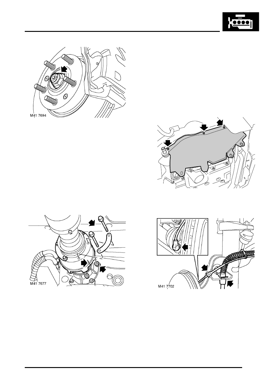
33. With an assistant depressing the brake pedal, 

remove and discard LH and RH drive shaft 
nuts.

34. Remove rear beam.


 + 

 FRONT SUSPENSION, REPAIRS, 

Rear beam.

35. Remove exhaust front pipe.


 + 

 MANIFOLDS & EXHAUST SYSTEMS 

- K SERIES KV6, REPAIRS, Front pipe - Non 
NAS.
 

 + 

 MANIFOLDS & EXHAUST SYSTEMS 

- K SERIES KV6, REPAIRS, Front pipe - NAS.

36. Raise one rear wheel for rotation of propeller 

shaft to access bolts.

37. Reference mark position of viscous coupling 

flange to IRD unit flange to aid reassembly.

38. Remove 6 nuts and bolts securing propeller 

shaft to IRD drive flange.

39. Release propeller shaft from IRD drive flange 

and tie shaft aside.

CAUTION: Care must be taken to support 
the Tripode joint when removed from the 
IRD unit. To avoid damage to gaiter or steel 
can, the joint should not be allowed to fully 
extend or be dropped.

40. Drain gearbox fluid.


 + 

 AUTOMATIC GEARBOX - JATCO, 

ADJUSTMENTS, Gearbox fluid - drain & 
refill.

41. Drain fluid from IRD.


 + 

 INTERMEDIATE REDUCTION 

DRIVE, ADJUSTMENTS, Intermediate 
reduction drive (IRD) fluid - drain & refill - 
Non NAS.
 

 + 

 INTERMEDIATE REDUCTION 

DRIVE, ADJUSTMENTS, Intermediate 
reduction drive (IRD) lubrication system - 
drain & refill - NAS.

42. Remove 6 bolts securing RH and LH front 

splash shields and remove shields.

43. Remove clips securing brake hoses to RH and 

LH damper brackets.

44. Release ABS sensor leads from bracket.
45. Release ABS sensors from RH and LH front 

hubs.

46. Remove nuts securing RH and LH track rod 

end ball joints.

47. Fit an M12 nut to each ball pin, flush with end of 

each pin.

M12 6614

ENGINE - K SERIES KV6

12-3-28 REPAIRS

48. Using LRT-57-043, separate ball pins from RH 

and LH steering arms. Remove M12 nuts and 
release ball pins from steering arms.

49. Pull RH and LH hubs outwards and release 

driveshafts from hubs.

50. Using LRT-54-026, release drive shafts from 

IRD unit and gearbox.

51. Remove nut securing selector lever to selector 

shaft on gearbox and release lever from 
selector shaft.

52. Release clip securing selector cable to gearbox 

bracket, remove cable and tie aside.

53. Using a 3/8” square drive socket bar, raise 

ancillary drive belt tensioner and release drive 
belt from  A/C compressor pulley.

ENGINE - K SERIES KV6

REPAIRS 12-3-29

54. Disconnect multiplug from A/C compressor.
55. Note fitted position of heat shield on A/C 

compressor and remove 3 bolts securing A/C 
compressor to front mounting plate and 
cylinder block. Release A/C compressor and 
heat shield and position aside.

56. Lower vehicle on ramp.

57. Using a hoist, connect adjustable lifting 

bracket, LRT-12-138 to engine.

58. Raise hoist to take weight without exerting any 

load on the engine mountings.

59. Remove through bolt securing LH engine 

mounting to gearbox bracket.

60. Remove 4 bolts securing LH mounting to body 

and remove mounting.

61. Remove 4 bolts securing LH mounting bracket 

to gearbox and remove bracket.

62. Using gearbox bracket bolts, secure LRT-44-

026 lifting bracket to gearbox.

M12 6789

M12 6788

ENGINE - K SERIES KV6

12-3-30 REPAIRS

63. Place a wooden block on jack, position jack 

under gearbox and raise jack sufficient to 
support weight of gearbox. Release lifting hook 
from rear engine lifting bracket and connect to 
lifting bracket on gearbox.

64. Remove bolt securing upper RH engine steady 

to top arm.

65. Loosen bolt securing upper RH engine steady 

to body, pivot engine steady away from top 
arm.

66. Remove bolt securing PAS pipe to engine front 

mounting plate.

67. Remove nut and 4 bolts securing engine top 

arm bracket to RH hydramount and to engine 
front mounting bracket.

68. Release PAS pipe support bracket from 

hydramount and position pipe aside.

69. Remove top arm.

70. Remove 3 Torx screws securing PAS pump 

pulley and remove pulley.

M12 6605


Content   ..  82  83  84  85   ..