Freelander 1. Manual - part 72


  Index      Land Rover     Freelander 1 - service manual 2002 year


Search            


Content   ..  70  71  72  73   ..


Freelander 1. Manual - part 72


ENGINE - K SERIES 1.8

OVERHAUL 12-2-61

Gasket - cylinder head  -  unit removed

$% 12.29.02.01

Remove

1. Remove camshaft timing belt rear cover. 


 + 

 ENGINE - K SERIES 1.8, REPAIRS, 

Cover - timing belt - rear.

2. Remove camshaft cover gasket.


 + 

 ENGINE - K SERIES 1.8, 

OVERHAUL, Gasket - camshaft cover.

3. Models with A/C: Release cover, loosen nut 

and disconnect battery lead from alternator. 
Disconnect multiplug from alternator.

4. Models with A/C: Remove upper and lower 

bolts securing alternator and remove alternator.

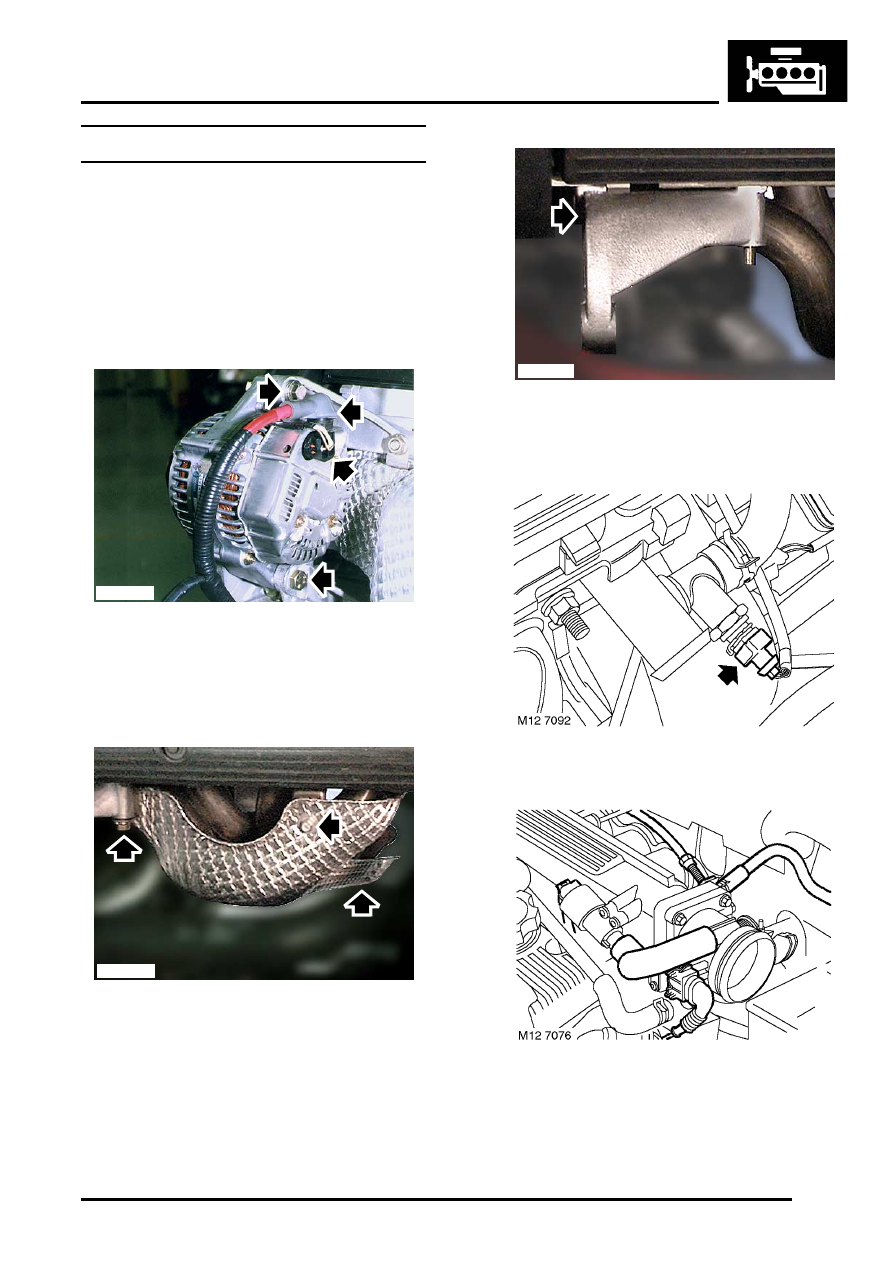
5. Models with A/C: Remove nut and 2 bolts 

securing heat shield to exhaust manifold and 
remove heat shield.

6. Models with A/C: Remove bolt securing 

alternator top support bracket to cylinder head 
and remove bracket.

7. Disconnect multiplug from ECT sensor.

8. Disconnect multiplug from TP sensor.

M12 7088

M12 7090

M12 7091        

ENGINE - K SERIES 1.8

12-2-62 OVERHAUL

9. Disconnect multiplug from IAT sensor.

10. Disconnect multiplug from IACV.

11. Disconnect multiplug from injector harness.
12. Temporarily fit timing gears to their respective 

camshafts, fit but do not fully tighten bolts.

13. Using tool LRT-12-182, rotate camshafts to 

access cylinder head bolts beneath camshaft 
reluctor rings.

14. Working in the sequence shown, progressively 

loosen cylinder head bolts.

15. Remove cylinder head bolts and store in fitted 

order.

16. Remove and discard cylinder head gasket.

CAUTION: Removal of cylinder head bolts 
results in a 'tightening up' of the crankshaft. 
Crankshaft rotation must, therefore, be kept 
to a minimum. Do not rotate crankshaft until 
cylinder liner clamps LRT-12-144 are fitted.

17. Identify type of locating dowels fitted, nylon 

dowels must be replaced with steel dowels.

ENGINE - K SERIES 1.8

OVERHAUL 12-2-63

18. Fit cylinder liner clamps LRT-12-144 to cylinder 

block and secure with cylinder head bolts. 
Make sure that feet of the cylinder liner clamps 
do not protrude over cylinder liner bores.

CAUTION: Ensure that bolts used are those 
originally fitted in that location.

Refit

1. Remove bolts securing cylinder liner clamps 

LRT-12-144 to cylinder block and remove 
clamps.

CAUTION: Keep bolts in their original fitted 
order. Do not rotate crankshaft with clamps 
removed.

2. Clean mating faces of cylinder head and 

cylinder block.

3. Check cylinder head and mating face of 

cylinder block for damage, pay particular 
attention to gasket face of cylinder head.

4. Ensure coolant and oil passages are clean.

5. Check cylinder head face for warping, across 

centre and from corner to corner as shown. 
 

 + 

 GENERAL DATA, Engine – K1.8 

Petrol.

Note: Cylinder head may be refaced provided 
height is kept within specified limits.

6. Wash cylinder head bolts and wipe dry.
7. Apply a light film of oil to bolt threads and 

underside of bolt heads.

8. Carefully enter cylinder head bolts in their 

original fitted location, DO NOT DROP. Tighten 
each bolt by hand into oil rail.

ENGINE - K SERIES 1.8

12-2-64 OVERHAUL

9. Measure distance from the cylinder block face 

to underside of bolt head 'A' in illustration:

l

97 mm (3.8 in) - Bolt may be re-used

l

Over 97 mm (3.8 in) - Bolt must be replaced

10. If nylon locating dowels were removed, clean 

dowel holes and fit new steel dowels to cylinder 
block.

11. Check that fitted height of dowels is between 10 

to 11 mm (0.40 to 0.43 in).

12. Fit new cylinder head gasket, dry, to cylinder 

block.

13. With assistance, fit cylinder head and carefully 

position cylinder onto dowels.

14. Clean camshaft timing gears.
15. Temporarily fit timing gears to camshafts, fit but 

do not fully tighten bolts.

16. Using tool LRT-12-182, rotate camshafts to 

gain access to cylinder head bolts beneath 
camshaft reluctor rings.

17. Carefully enter cylinder head bolts in their 

original fitted order, DO NOT DROP. Tighten 
bolts into place by hand.

18. Working in the sequence shown, progressively 

tighten the cylinder head bolts to: 

l

Stage 1 - 20 Nm (15 lbf.ft)

l

Stage 2 - 180

°

l

Stage 3 - Further 180

°

CAUTION: Do not tighten bolts 360

°

 in one 

operation.

19. Remove camshaft timing gears.
20. Fit camshaft timing belt rear cover. 


 + 

 ENGINE - K SERIES 1.8, REPAIRS, 

Cover - timing belt - rear.

21. Fit camshaft cover gasket.


 + 

 ENGINE - K SERIES 1.8, 

OVERHAUL, Gasket - camshaft cover.

22. Connect multiplugs to IACV, IAT, TP and ECT 

sensors. Connect multiplug to injector harness.

23. Models with A/C: Position alternator support 

bracket, fit and tighten bolt to 25 Nm (18 lbf.ft).

24. Models with A/C: Position heat shield to 

exhaust manifold. Fit and tighten nut to 25 Nm 
(18 lbf.ft) and bolts to 10 Nm (7.5 lbf.ft).

25. Models with A/C: Position alternator, fit upper 

and lower bolts and tighten to 45 Nm (33 lbf.ft).

26. Models with A/C: Position battery cable to 

alternator and tighten nut to 8 Nm (6 lbf.ft).

27. Models with A/C: Connect multiplug to 

alternator.


Content   ..  70  71  72  73   ..