Freelander 1. Manual - part 10
GENERAL DATA
04-1
GENERAL DATA
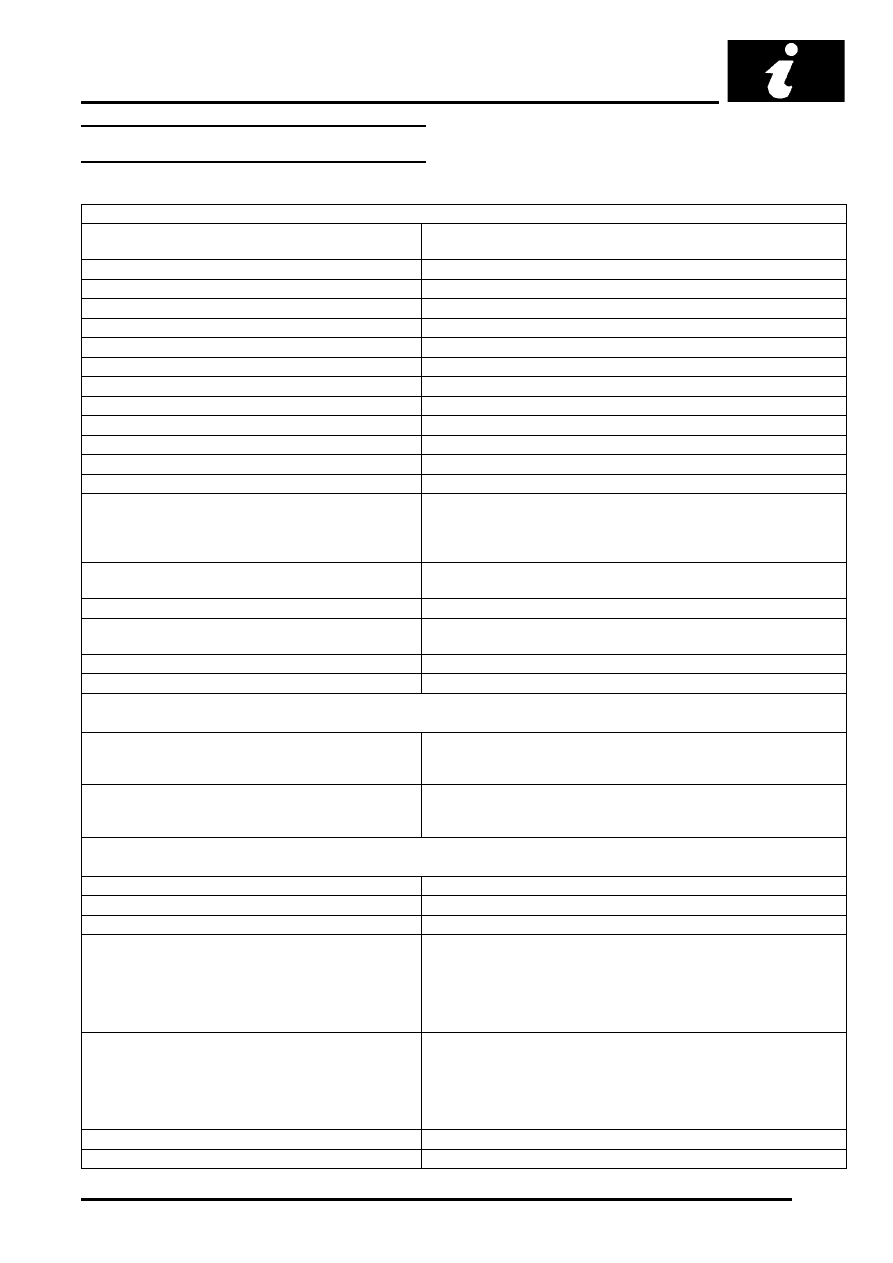
Engine – Td4 Diesel
General
Type
2.0 litre in-line direct injection diesel, 16-valve, DOHC, turbocharged
and intercooled
Cylinder arrangement
4 in-line, transverse, No.1 cylinder at front of engine
Bore
84.00 mm (3.307 in.)
Stroke
88.00 mm (3.465 in.)
Capacity
1951 cm
3
(119.05 in
3
)
Firing order
1-3-4-2
Compression ratio
18:1
±
0.5:1
Direction of rotation
Clockwise, viewed from the front of the engine
Maximum power
82 kW (112 bhp) @ 4000 rev/min.
Maximum torque
260 Nm (192 lbf.ft) @ 1750 rev/min.
Maximum governed speed
4800 rev/min.
Maximum overrun speed
5250 rev/min
Idle speed
780
±
30 rev/min
Dimensions:
⇒
Length
⇒
Width
⇒
Height
482 mm (19.0 in)
634 mm (25.0 in)
697 mm (27.4 in)
Glow plugs:
4 off, one per cylinder arranged centrally on inlet side between inlet
valves
Turbocharger
Mitsubishi MR1 TD025L3 - 08T - 3.3
Fuel injection system:
Common rail, direct injection fed by Bosch high pressure delivery
pump
Injection timing
Controlled by ECM
Emissions standard
ECD3
Valve timing
Inlet valves:
⇒
Opens
⇒
Closes
8
°
BTDC
28
°
ABDC
Exhaust valves:
⇒
Opens
⇒
Closes
38
°
BBDC
4
°
ATDC
Lubrication
Type
Wet aluminium die-cast sump, pressure fed
Oil filter
Disposable canister with full flow by-pass
Oil cooler
Integral with oil filter assembly, connected to vehicle cooling system
Oil pump:
⇒
Type
Crankshaft driven, eccentric rotor
⇒
Oil flow rate
30 litres / min. (6.625 gallons/min.)
⇒
Outer rotor to body clearance
0.080 - 0.158 mm (0.0031 - 0.062 in.)
⇒
Peak pressure
up to 20 bar (290 lbf.in
2
)
Oil pressure at idle:
⇒
Cold - 1000 rev/min.
1.5 bar (21.8 lbf.in
2
)
⇒
Operating temperature (minimum)
0.5 bar (7.3 lbf.in
2
)
⇒
Regulated pressure
4.2
±
0.5 bar (60.9
±
7.3 lbf.in
2
)
⇒
Pressure at 3500 rev/min (hot)
3.0 - 4.5 bar (43.5 - 65.3 lbf.in
2
)
Relief valve opening pressure
4.2 bar (60.9 lbf.in
2
)
Low oil pressure switch opening pressure
0.2 - 0.5 bar (2.9 - 7.3 lbf.in
2
)