Discovery 2. Manual - part 754
WINDOWS
REPAIRS 86-5-13
REPAIRS
Switch - rear door
$% 86.25.10
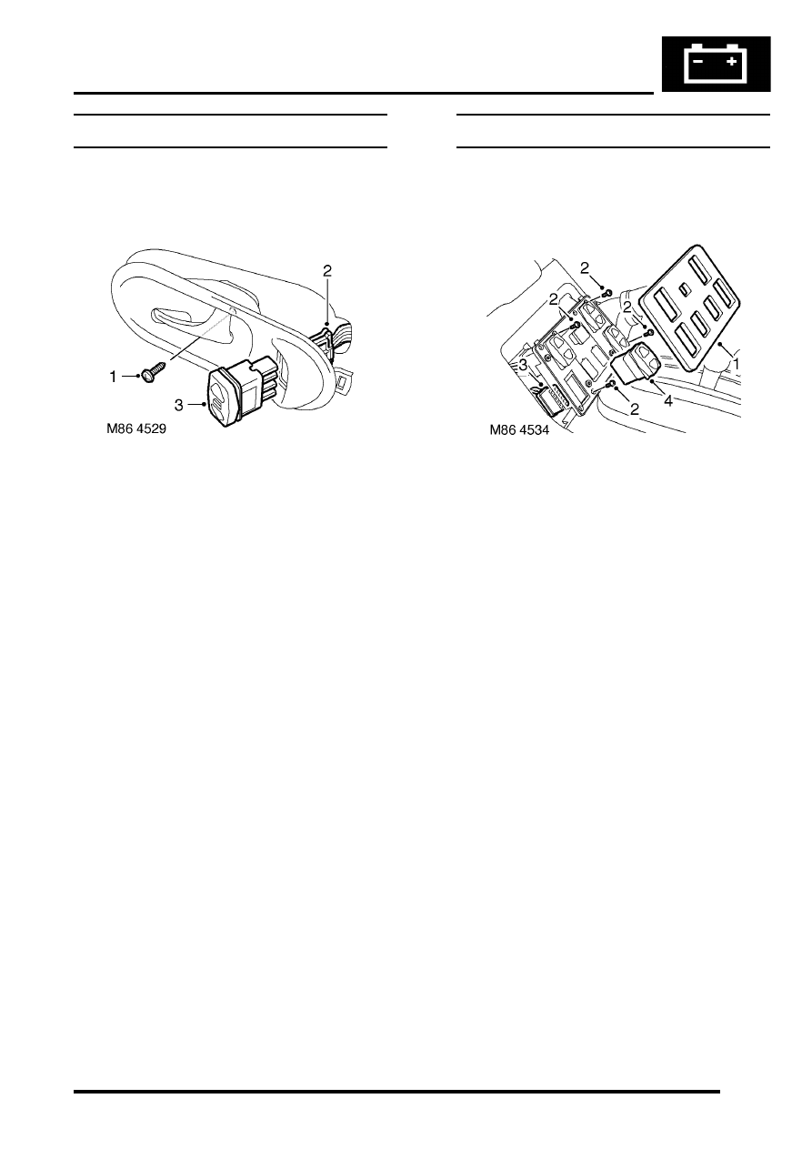
Remove
1. Remove screw securing escutcheon to door
casing.
2. Release escutcheon, far enough to access
switch multiplug, and disconnect multiplug
from switch.
3. Remove switch from escutcheon.
Refit
1. Connect new switch to multiplug and fit to
escutcheon.
2. Fit escutcheon to door casing and secure with
screw.
Switch - console
$% 86.25.19
Remove
1. Remove console switch cover.
2. Remove 4 screws securing switch mounting
plate to console.
3. Release mounting plate from console and
disconnect multiplug from switch.
4. Release and remove switch from mounting
plate.
Refit
1. Fit new switch to mounting plate and connect
multiplug.
2. Position mounting plate and secure with
screws.
3. Fit console switch cover.