Discovery 2. Manual - part 724


  Index      Land Rover     Land Rover Discovery 2 - service manual 1999 year


Search            


Content   ..  722  723  724  725   ..


Discovery 2. Manual - part 724


WIPERS AND WASHERS

DESCRIPTION AND OPERATION

84-11

The dc motor contains two permanent magnets, three brushes and a park switch. The smaller third brush is utilised 
for high-speed operation. Attached to the brush pack are 3 capacitors, which minimise radio interference during wiper 
operation. A thermal trip switch attached to the brush plate prevents thermal overload of the motor.

The motor incorporates a worm drive gear unit to transfer the rotary motion into a linear motion of the wiper linkage 
assembly.

The front wiper motor receives battery voltage from fuse 19 of the passenger compartment fuse box.  For low-speed 
operation, including intermittent variable delay operation, the battery voltage to move the wiper motor from the park 
position passes through the front wiper relay.  When the park switch moves to the closed when operating position, 
fuse 19 of the passenger compartment fuse box provides battery voltage directly to the wiper motor.

For high-speed operation, including flick wipe, fuse 19 in the passenger compartment fuse box provides the battery 
voltage to move the wiper motor from the park position through the front wash/ wipe switch to the front wiper motor.  
To achieve high-speed wiper operation, power is supplied to a third brush that provides a closer distance between the 
motor poles.  Because the poles of the motor are closer together, the motor operates faster.

Rear wiper
The rear wiper is driven directly from an electric motor located inside the tail door. The motor is mounted inside the 
tail door with two bolts, lock washers and washers. The motor mounting brackets have rubber inserts to prevent motor 
operating noise being transferred to the door structure. The motor spindle is fitted with a seal and protrudes through 
a hole in the tail door outer skin panel. The motor spindle is secured to the tail door with a washer and nut.

The motor output spindle has a taper splined shaft which allows for the attachment of the wiper arm which is secured 
with a nut. The wiper arm attachment to the splined shaft has a pivot to which the remainder of the arm is attached. 
The two parts of the arm are connected by a spring which controls the pressure of the blade on the window to a 
predetermined amount.

The wiper blade is attached to the wiper arms with a clip which allows the blade to pivot. The wiper blade comprises 
of a number of levers and yokes to which the rubber wiper is attached. The levers and yokes ensure that the pressure 
applied by the arm spring is evenly distributed along the full length of the blade. The rubber wiper is held in the yokes 
by a pair of stainless steel strips which also contribute to the even distribution of spring pressure along the blade.
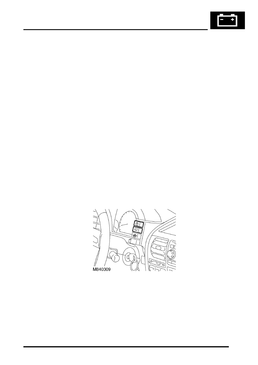
Rear wiper switch

The rear wiper switch is a latching pushbutton switch and is located on the right hand side of the instrument pack.

Activating the rear wiper switch provides an earth signal to the BCU.  The BCU signals the IDM to energise the rear 
wiper relay, which provides battery voltage to the rear wiper motor.

WIPERS AND WASHERS

84-12

DESCRIPTION AND OPERATION

Rear wiper motor

The DC motor contains two permanent magnets and a park switch.  An earth braid attached between the motor casing 
and the brush pack is utilised to minimise radio interference during wiper functions.

The rear wiper switch provides an earth signal to the BCU, which determines the delay interval, if appropriate.  The 
BCU then signals the IDM to activate the rear wiper motor relay, which provides power to the rear wiper motor.

To allow the rear wiper to park when the rear wiper is switched off, power flows through the park switch until a cam 
in the wiper motor assembly breaks the contact of the park switch.  Triggering the park switch grounds the positive 
side of the wiper motor causing it to stop abruptly

Washers
The washer system comprises a reservoir, washer pumps, hoses and washer jets. The front washers are controlled 
from a stalk switch on the steering column and the rear washers are operated by a non-latching pushbutton switch on 
the fascia adjacent to the instrument pack.

Reservoir
The reservoir is located behind the front bumper in the inner wheel arch and has a capacity of 6.0 litres (12.5 US pints). 
A filler neck tube is connected to the reservoir with a seal and extends into the engine compartment on the front left 
hand side. The filler neck tube contains a removable filter to prevent particle contamination and a yellow float to show 
reservoir contents. The washer filler neck tube is sealed with a cap which is coloured blue for identification.

Two electric washer pumps are located on the rear face of the reservoir and supply washer fluid to the front 
windscreen and the tail door window. Each pump is sealed to the reservoir with a rubber sealing grommet. 

On vehicles with headlamp powerwash fitted, a third pump is fitted with a sealing grommet to the front face of the 
reservoir.

The reservoir and filler neck tube are manufactured from moulded opaque nylon. The reservoir has moulded lugs for 
attachment to the vehicle body. A bracket is attached to the top of the filler neck tube and locates in a hole in the body 
to secure the top of the tube.

WIPERS AND WASHERS

DESCRIPTION AND OPERATION

84-13

Front screen washer jets
Two washer jets for the front windscreen are fitted to the top surface of the bonnet and held in place with plastic clips. 
Each washer jet is connected via a hose to an in-line valve. The in-line valve prevents the washer fluid draining back 
to the reservoir and ensures that the washers operate immediately the washer pump is operated. From each in-line 
valve the washers are connected via a short hose to a 'T' connector. From the 'T' connector a single hose connects 
to the outlet of the front washer pump. Each jet has two jets which can be adjusted to allow full fluid coverage of the 
windscreen.

Rear screen washer jet
A single washer jet for the tail door window is fitted to the rear wiper blade. The jet has four spray orifices which direct 
washer fluid to either side and along the length of the wiper blade. The jet is connected by a hose from the wiper blade, 
through a sealing grommet in the tail door and connects with the rear washer hose from the rear washer pump. A non-
return valve is used to join the feed hose from the pump to the washer jet hose. The non-return valve prevents fluid 
draining to the reservoir and ensures that the washer operates immediately the washer pump is operated. The hose 
from the pump to the tail door is located inside the main harness.

Headlamp power washer jets
When fitted, a powerwash jet for each headlamp is located in a housing on the top surface of the front bumper. The 
jets are fed with fluid at high pressure from the powerwash pump. A large diameter hose connects each jet to the 
pump. Each connection is secured with a metal clip to secure the hose due to the high pressure from the pump. Each 
jet directs the high pressure fluid in a wide spray onto the headlamp lens.

Rear washer switch

The rear washer switch is a non-latching pushbutton switch and is located on the RH side of the instrument pack.

Activating the rear washer switch provides battery voltage from fuse 30 in the passenger compartment fusebox to the 
rear washer pump.

WIPERS AND WASHERS

84-14

DESCRIPTION AND OPERATION

Front washer pump

The front washer pump consists of a DC motor with an impeller. It is located in the rear of the washer fluid reservoir 
and can be identified by its black top.

Operating the front washer switch provides battery voltage to the front washer pump.  This same battery voltage signal 
also goes to the BCU and increments the headlamp powerwash counter providing the headlamps are switched on.

Rear washer pump 

The rear washer pump consists of a DC motor with an impeller. It is located in the rear of the washer fluid reservoir 
and can be identified by its red top.

Operating the rear washer switch provides battery voltage to the rear washer pump.


Content   ..  722  723  724  725   ..