Discovery 2. Manual - part 607


  Index      Land Rover     Land Rover Discovery 2 - service manual 1999 year


Search            


Content   ..  605  606  607  608   ..


Discovery 2. Manual - part 607


FRONT SUSPENSION

DESCRIPTION AND OPERATION

60-25

Operation

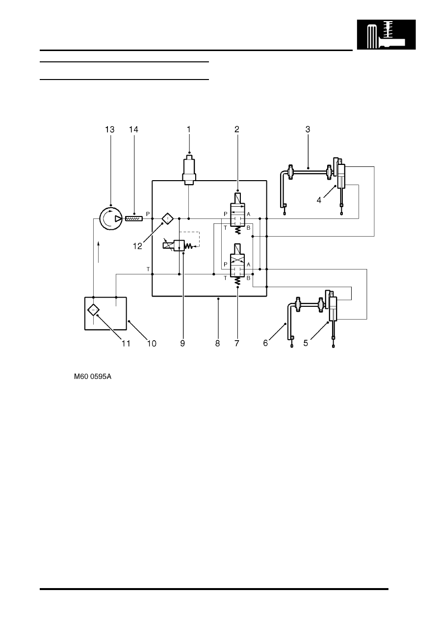
Hydraulic circuit diagram

Pressure transducer
Directional control valve 2
Front torsion bar assembly
Actuator
Actuator
Rear torsion bar assembly
Directional control valve 1

Valve block
Pressure control valve

10 Reservoir
11 Filter
12 High pressure filter
13 Hydraulic pump
14 Attenuator hose

Vehicle not moving
When the engine is running and the vehicle is not moving, both DCV's are closed, locking fluid in each side of the 
actuator pistons. The hydraulic pump draws fluid from the reservoir and passes it at very low pressure to the valve 
block. Because both DCV's are closed, after the fluid passes through the high pressure filter, it is directed through the 
pressure control valve to the reservoir. The pressure control valve is open fully to allow the full flow to pass to the 
reservoir. The DCV's will remain closed until the ECU detects a need to operate.

FRONT SUSPENSION

60-26

DESCRIPTION AND OPERATION

Vehicle moving and turning left
When the vehicle is turning left, the accelerometers detect the cornering forces applied and transmit signals to the 
ECU. The ECU determines that an opposing force must be applied to the torsion bars to counter the cornering forces. 
The ECU supplies a current to the solenoid of the DCV2. Simultaneously, a current is sent from the ECU to the 
pressure control valve which operates to restrict the flow of fluid returning to the reservoir.

The restriction causes the hydraulic pressure in the system to rise and the pressure is sensed by the pressure 
transducer which sends a signal to the ECU. The ECU determines from the inputs it receives what pressure is required 
and adjusts the pressure control valve accordingly.

The pressure in the system is applied to the annulus of each actuator, applying an opposing force to the torsion bar 
and minimising the cornering effect on the vehicle and maintaining the vehicle attitude. The fluid displaced from the 
full area of the actuator is returned to the reservoir via the valve block.

As the cornering force is removed when the vehicle straightens up, the ECU opens the pressure control valve to 
reduce the pressure in the system. The fluid bleeds from the actuator back into the system as the cornering force is 
reduced, removing the force from the torsion bar. When the vehicle is moving in a straight line DCV 2 closes.

Vehicle moving and turning right
When the vehicle is turning right, the accelerometers detect the cornering forces applied and transmit signals to the 
ECU. The ECU determines that an opposing force must be applied to the torsion bars to counter the cornering forces. 
The ECU supplies a current to the solenoid of the DCV1. Simultaneously, a current is sent from the ECU to the 
pressure control valve which operates to restrict the flow of fluid through the by-pass gallery.

The restriction causes the hydraulic pressure in the system to rise and the pressure is sensed by the pressure 
transducer which sends a signal corresponding to the pressure to the ECU. The ECU determines from the inputs it 
receives what pressure is required and adjusts the pressure control valve accordingly.

The pressure in the system is applied to the full area of each actuator, applying an opposing force to the torsion bar 
and minimising the cornering effect on the vehicle and maintaining the vehicle attitude. The fluid displaced from the 
annulus of the actuator is returned to the reservoir via the valve block.

As the cornering force is removed when the vehicle straightens up, the ECU opens the pressure control valve to 
reduce the pressure in the system. The fluid bleeds from the actuator back into the system as the cornering force is 
reduced, removing the force from the torsion bar. When the vehicle is moving in a straight line the DCV 1 closes.

Vehicle moving in a straight line
The ECU is constantly monitoring the signals received from the accelerometers and operates the DCV's and pressure 
control valve to maintain the vehicle attitude when the vehicle is moving.

Off-road driving
Off-road detection is achieved by the ECU by monitoring the signals from the upper and lower accelerometers for 
varying degrees of body movement. Off-road driving generates differing signals to the accelerometers which in turn 
produce differing outputs due to their vertical separation and the location of the roll centre of the vehicle. The two 
signals are passed through a filter to remove any offset caused by the vehicle leaning or the terrain. The ECU then 
uses this signal to calculate the percentage of road roughness.

Below 25 mph (40 km/h) the percentage of road roughness calculated is used by the ECU to limit the operation of the 
ACE system. The system is completely inoperative at speeds below 2 mph (3 km/h). At speeds above 25 mph (40 
km/h) the system disables the percentage road roughness signal and full ACE system assistance is restored.

Side slope detection
The ECU uses side slope detection when the upper and lower accelerometers detect an average acceleration of more 
than 

±

 0.2 g and a road speed of less than 25 mph (40 km/h).

When side slope is detected both DCV's close to provide a 'locked bars' condition. This condition increases stability 
and gives a consistent vehicle response. As the road speed increases up to 25 mph (40 km/h), the level of average 
lateral acceleration must also increase and be maintained for the system to recognise that the vehicle is on a side 
slope. If the side slope angle is steep and the road speed is low, the ECU will detect the side slope in a short time.

FRONT SUSPENSION

ADJUSTMENTS

60-27

ADJUSTMENTS

ACE hydraulic system bleeding 

$% 60.60.13 

Introduction

CAUTION: The ACE hydraulic system is 
extremely sensitive to the ingress of dirt or 
debris. The smallest amount could render the 
system unserviceable. It is imperative that the 
following precautions are taken. 

l

ACE components are thoroughly cleaned 
externally before work commences;

l

all opened pipe and module ports are 
capped immediately;

l

all fluid is stored in and administered 
through clean containers.

Check

1. Check the ACE system fluid level. 


 + 

 FRONT SUSPENSION, 

ADJUSTMENTS, Fluid level check - ACE 
system.

Bleed

1. With vehicle on ramp, connect TestBook and 

follow bleed procedure as described.

Fluid level check - ACE system

$% 60.60.14 

Introduction

CAUTION: The ACE hydraulic system is 
extremely sensitive to the ingress of dirt or 
debris. The smallest amount could render the 
system unserviceable. It is imperative that the 
following precautions are taken. 

l

ACE components are thoroughly cleaned 
externally before work commences;

l

all opened pipe and module ports are 
capped immediately;

l

all fluid is stored in and administered 
through clean containers.

Check

1. Clean reservoir around fluid level marks. 
2. Visually check fluid level through side of 

reservoir. Fluid level must be between upper 
and lower fluid level marks.

Top-up

1. Clean reservoir around filler cap.
2. Remove filler cap from reservoir and fill to 

upper fluid level mark with recommended fluid. 
 

 + 

 CAPACITIES, FLUIDS AND 

LUBRICANTS, Fluids.

3. Fit filler cap to reservoir
4. Start and run engine for 2 minutes to circulate 

fluid.

5. If necessary, top-up reservoir to upper fluid 

level mark.

FRONT SUSPENSION

60-28

ADJUSTMENTS


Content   ..  605  606  607  608   ..