Discovery 2. Manual - part 561


  Index      Land Rover     Land Rover Discovery 2 - service manual 1999 year


Search            


Content   ..  559  560  561  562   ..


Discovery 2. Manual - part 561


TRANSFER BOX - LT230SE

OVERHAUL

41-47

Inspect

1. Check mating surfaces of cross shaft and 

housing bore for wear.

2. Check core plug in housing for signs of leakage 

or corrosion ; apply Loctite 326 to replacement 
plug.

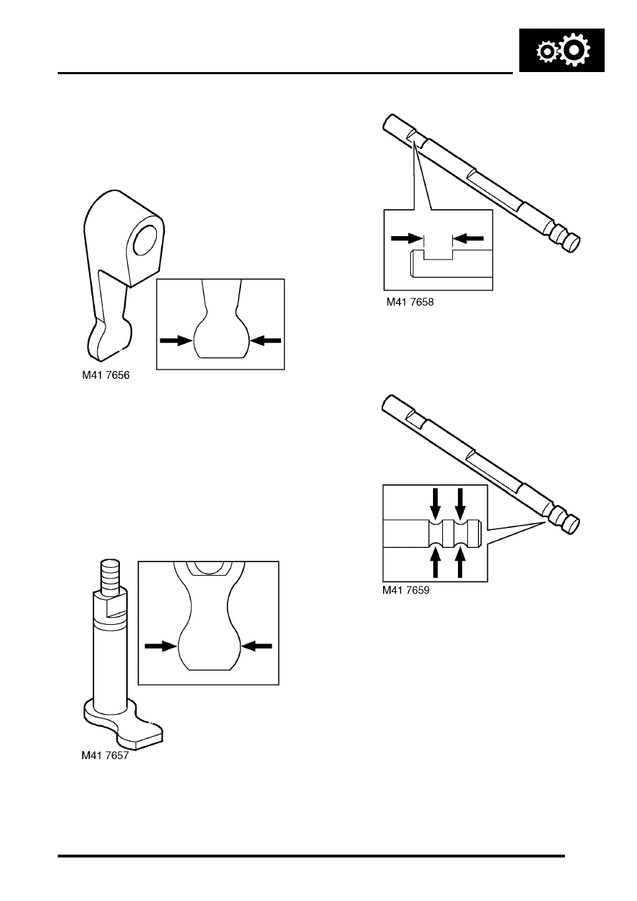
3. Measuring across widest portion of finger, 

check high/low selector finger for wear.

l

Finger width = 15.90 to 15.95 mm (0.625 to 
0.627 in).

4. Check bearing track recesses in housing for 

damage, rectify or replace housing as 
necessary.

5.  If fitted:  Carry out inspection of differential 

lock  components using following procedures.

6. Check differential lock selector shaft and 

housing bore for wear.

7. Measuring across the widest portion, check 

differential lock finger for wear.

l

Finger width = 15.90 to 15.95 mm (0.625 to 
0.627 in).

8. Check differential lock selector finger groove in 

selector shaft.

l

Groove width = 16.0 to 16.1 mm (0.63 to 
0.64 in).

9. Check detent grooves in differential lock 

selector shaft for wear.

10. Check differential lock detent ball for flat spots 

and check detent spring for distortion.

TRANSFER BOX - LT230SE

41-48

OVERHAUL

11. Check differential lock selector fork for cracks 

and wear.

12. Check selector fork finger width.

l

Finger width = 7.92 to 7.97 mm (0.311 to 
0.313 in).

13. Check differential lock selector fork clips for 

wear and damage. Check spring for distortion 
and free length.

l

Spring free length = 84.58 mm (3.33 in).

14. Check dog clutch internal teeth and grooves 

and teeth on output shaft for wear and  
damage. Check selector fork groove width.

l

Groove width = 8.05 to 8.20 mm (0.32 to 
0.33 in).

15. Carry out the following inspection procedures 

for all transfer boxes.

16. Check threads and splines of output shaft for 

damage and wear. Check dog clutch teeth on 
shaft for wear and damage.

17. 03 MY onwards: Compress high/low selector 

fork spring and remove retaining clips from 
each end of spring, remove high/low selector 
shaft.

18. Check detent grooves in high/low selector shaft 

for wear. Do not remove fork from shaft 
unless either component is being renewed. 
If fork is removed from shaft, coat the 
threads of the set screw with Loctite 290 
prior to assembling.

Note: High/low selector shaft fitted to pre 03 MY 
illustrated.

TRANSFER BOX - LT230SE

OVERHAUL

41-49

19. Check width of high/low selector groove.

l

Groove width = 16.0 to 16.1 mm (0.63 to 
0.64 in).

20. Check high/low selector fork for cracks and 

wear. Check selector fork finger width.

l

Finger width = 7.37 to 7.47 mm (0.290 to 
0.294 in).

21. 03 MY onwards: Check high/low selector fork 

clips for wear and damage. Check spring for 
distortion, check free length of spring:

l

Spring free length = 75 mm (2.95 in)

Note: High/low selector shaft, fork and spring 
fitted to 03 MY transfer boxes may be fitted to 
pre 03 MY boxes as an assembly.

22. Check differential sun and planet gears for 

wear, cracks and chipping of teeth.

23. Check cross shafts and recesses in both halves 

of differential carrier for damage and 
wear.Ensure planet gears are retained with 
their respective shafts.

24. Check retaining ring for distortion.
25. Check differential splines for wear and 

damage.

26. Check high/low hub for cracks, chipping and 

uneven wear. Check width of selector fork 
groove. 

l

Groove width = 7.5 to 7.6 mm (0.295 to 0.30 
in).

27. Check splines and teeth on high/low selector 

sleeve for uneven wear, cracks, damage and 
chipping.

28. Check teeth of high and low range gears for 

cracks, chipping and uneven wear.

29. Check high range gear bush for wear and 

damage.

Reassembly

1. Lubricate all components with recommended 

oil and lightly oil the differential bolt threads.

TRANSFER BOX - LT230SE

41-50

OVERHAUL

2. Secure rear half of differential carrier in a soft 

jawed vice.

3. Fit each planet gear to its respective cross 

shaft, fit new dished thrust washer to each 
gear.

4. Fit cross shafts, planet gears and dished thrust 

washers in rear half of carrier.Ensure that 
cross shafts are fitted correctly. Do not fit 
the sun gear into the rear half carrier at this 
stage.

5. Fit retaining ring.
6. Fit a 1.05 mm (0.04 in) thrust washer to sun 

gear from front half of carrier. Position gear in 
front half of carrier.

7. Ensuring that assembly marks are aligned, fit 

both halves of carrier together. 

8. Fit the differential carrier bolts and, working in a 

diagonal sequence, tighten the bolts to 60 Nm, 
(44 lbf.ft).

9. Insert the front output shaft into the front half of 

the carrier and check that the gears rotate 
freely.

10. Fit output flange on to the splines of the output 

shaft, but do not fit flange nut at this stage.

11. Fit transmission brake drum to output flange 

and secure the drum using 2 nuts.

12. Secure a length of cord around the drum and 

attach one end of the cord to a spring balance.

13. Pull on the spring balance and note the load at 

which the brake drum starts to turn. Used 
gears should rotate smoothly, while new 
gears will have a 'notchy' feel as they rotate.

14. Compare the figure obtained with the following.

l

Used gears = 0.45 kg (1.0 lb)

l

New gears = 1.72 kg (3.8 lb)

15. If the load to turn figure is below the specified 

limits, proceed as follows.

16. Remove the front output shaft and brake drum.
17. Remove the 8 bolts securing the two halves of 

the differential carrier

18. Separate the differential carrier and remove the 

sun gear and thrust washer from the front half.

19. Select a thicker thrust washer from the range 

available. 5 different thrust washers are 
available, rising in increments of 0.10 mm 
(0.004 in) from 1.05 mm to 1.45 mm (0.04 to 
0.06 in).

20. Repeat steps 7 to 19 as necessary until the 

load to turn figure is as specified

21. When specified load to turn is obtained, 

proceed as follows.

22. Remove the front output shaft and brake drum.
23. Remove the 8 bolts securing the two halves of 

the differential carrier

24. Separate the differential carrier and remove the 

sun gear and thrust washer from the front 
half.Retain the selected thrust washer with 
its sun gear.


Content   ..  559  560  561  562   ..