Discovery 2. Manual - part 504


  Index      Land Rover     Land Rover Discovery 2 - service manual 1999 year


Search            


Content   ..  502  503  504  505   ..


Discovery 2. Manual - part 504


FUEL DELIVERY SYSTEM - TD5

DESCRIPTION AND OPERATION

19-1-7

The fuel pressure regulator is located in a cast alloy housing which is attached to the rear right hand corner of the 
cylinder head with three flanged bolts and sealed with a metal gasket. On pre EU3 models there are two ports in the 
housing that connect with ports in the cylinder head for fuel pressure feed and return. On EU3 models there is a port 
in the housing that connects with a port in the cylinder head for fuel pressure feed and a single external port for fuel 
return. A gauze filter is located in the pressure feed port in the cylinder head and filters the fuel before it reaches the 
injectors. The filter is a fit for life item but can be changed if required. An 'O' ring is located in a recess in the cylinder 
head and provides additional sealing for the pressure feed port between the gauze filter, the cylinder head and the 
housing.

A union and pipe is attached to the feed port in the housing and connects with a quick release coupling to the fuel 
pressure feed pipe from the fuel pump. A second union and hose is located in the return port and provides the fuel 
return connection to the fuel cooler. A third port provides location for the fuel temperature sensor which is sealed to 
the housing with a bonded seal. The fuel temperature sensor is used by the Engine Control Module (ECM) for engine 
management.

The fuel pressure regulator is located in a machined port in the lower part of the housing. The regulator is sealed in 
the housing with two 'O' rings and secured with an internal circlip.

The regulator maintains the fuel pump delivery pressure at 4 bar (58 lbf.in

2

). When the fuel pressure exceeds 4 bar 

(58 lbf.in

2

), the regulator opens and allows fuel to return to the fuel tank via the fuel cooler. The fuel returned from the 

regulator is directed back into the fuel filter before being drawn by the high pressure stage of the fuel pump and 
directed back to the injectors. A special tool can be attached to the regulator housing fuel feed port and allows for the 
fitment of a suitable gauge to measure fuel pump delivery pressure.
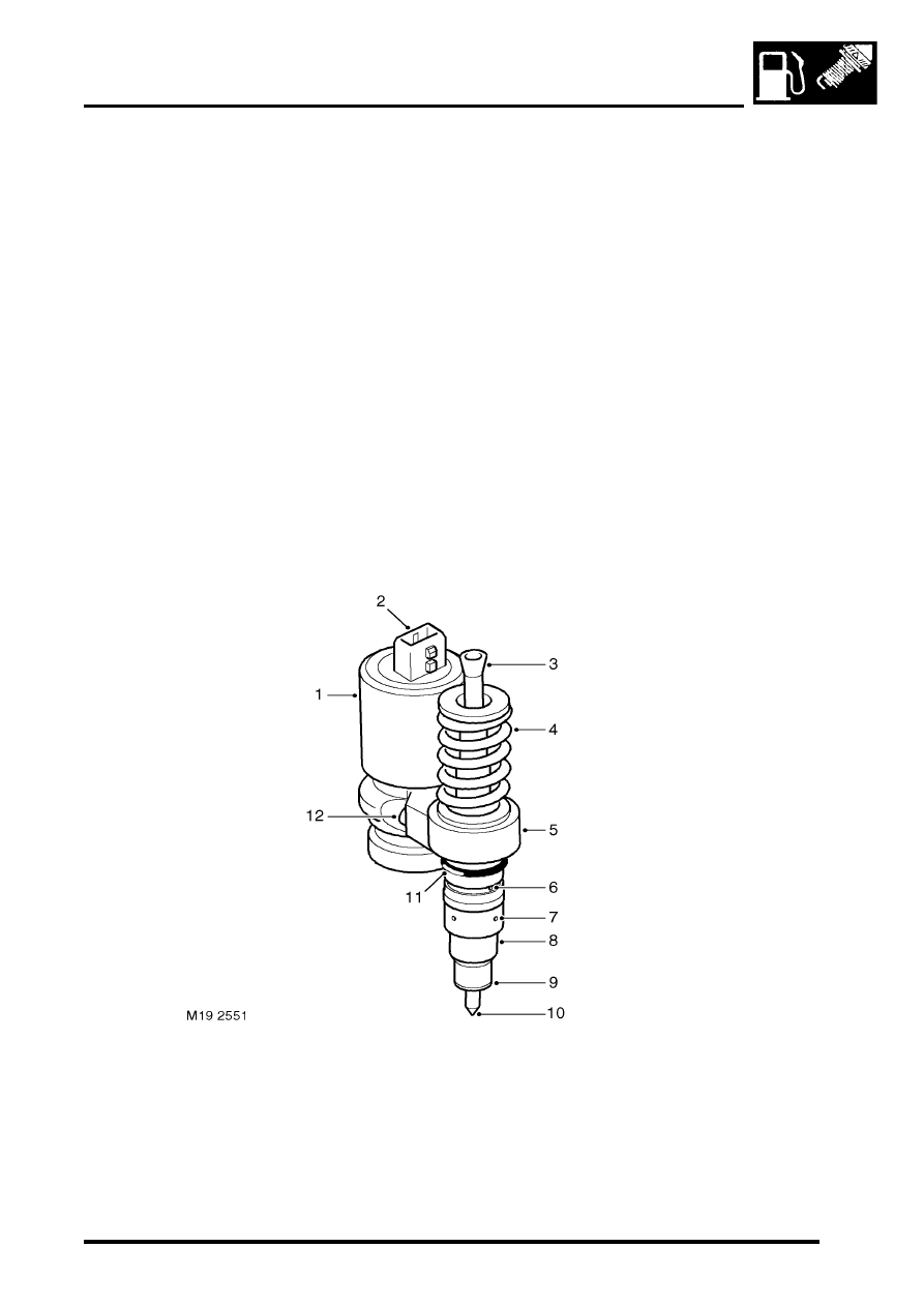
Injectors

Solenoid housing
Electrical connector
Push rod socket
Push rod return spring
Housing
Fuel delivery port

Fuel return port
Nozzle cap nut
Copper washer

10 Nozzle
11 'O' ring
12 Cap screw 2 off

FUEL DELIVERY SYSTEM - TD5

19-1-8

DESCRIPTION AND OPERATION

The five injectors are located in the cylinder head, adjacent to the camshaft, with the nozzle of each injector protruding 
directly into the cylinder. Each injector is sealed into the cylinder head with an 'O' ring and a copper washer and 
secured with a clamp and bolt.

Each injector is operated mechanically by an overhead camshaft and rocker and electrically by a solenoid controlled 
by the ECM. Each injector is supplied with pressurised fuel from the pump via the regulator housing and internal 
drillings in the cylinder head.
 

 + 

 ENGINE MANAGEMENT SYSTEM - Td5, DESCRIPTION AND OPERATION, Description.

The solenoid housing is secured to the injector body with two cap screws and is a sealed unit with a two pin electrical 
connector on its top face.

The injector body is machined from a forging. The body has a machined central bore which locates the push rod. A 
thread on the outer diameter provides the attachment for the nozzle cap nut. The body also provides attachment for 
the solenoid housing.

The injector push rod is operated from the rocker and cam assembly by a socket. The push rod is located in the 
housing bore and retained in its extended position by a push rod return spring. The powerful spring ensures that the 
push rod socket is always in contact with the rocking lever and the cam.

The lower part of the injector housing locates the spring loaded nozzle. The nozzle is retained in the housing by a 
nozzle cap nut which is screwed onto the housing. The nozzle cap nut has four holes around its circumference which 
connect to the fuel return drilling in the cylinder head. The injector housing has ports located above the nozzle cap 
nut which connect with the fuel delivery drilling in the cylinder head. An 'O' ring seals the injector in the machined 
location in the cylinder head and a copper washer seals the injector from the combustion chamber.

The injectors are supplied with pressurised fuel from the fuel pump, via the pressure regulator housing and internal 
drillings in the cylinder head. Each injector sprays fuel directly into the cylinder at approximately, 1500 bar (22000 
lbf.in

2

) on pre EU3 models and 1750 bar (25500 lbf.in

2

) on EU3 models, atomising the fuel and mixing it with intake 

air prior to combustion.

The camshaft and rocker arrangement depresses the push rod which pressurises the fuel within the injector. When 
the injector is required to inject fuel into the cylinder, the ECM energises the solenoid which closes a valve within the 
solenoid housing. The closure of the valve stops the fuel entering the return line to the pump, trapping it in the injector. 
The compression of the fuel by the push rod causes rapid pressurisation of the fuel which lifts the injector nozzle, 
forcing the fuel into the cylinder at high pressure. The ECM controls the injection timing by altering the time at which 
the solenoid is energised and the injection period by controlling the period for which the solenoid is energised.
 

 + 

 ENGINE MANAGEMENT SYSTEM - Td5, DESCRIPTION AND OPERATION, Description.

FUEL DELIVERY SYSTEM - TD5

DESCRIPTION AND OPERATION

19-1-9

Fuel filter

Filter body
Nut 2 off
Bolt 2 off
Rubber washer
Water sensor

Filter element
Air bleed valve
Air bleed connection
Copper washer 4 off

10 Connector 3 off

The fuel filter is located at the rear of the vehicle, to the right of the fuel tank and is attached by a bracket with two 
bolts and nuts to the right hand chassis longitudinal.

The filter has four quick release coupling connections; low pressure feed from the fuel pump, low pressure return to 
the fuel pump, return line from the fuel pressure regulator and a bleed line to the fuel pump. The fuel filter removes 
particulate matter from the fuel and also separates water which accumulates at the bottom of the filter.

An air bleed valve is located in the bleed line connection. The valve comprises a restrictor and a membrane. The 
restrictor has a small hole in its centre. This allows air and fuel to pass through the membrane. Air can pass through 
the membrane, but once the membrane is wet with fuel it will not allow further fuel to pass through.

The fuel filter has a replaceable screw-on canister type filter element which is sealed to the filter body with rubber 
seals. The lower part of the canister has a screw connection for a water sensor. The filter has a flow rate of 180 litres/
hour (47.6 US Gallons/hour).

FUEL DELIVERY SYSTEM - TD5

19-1-10 DESCRIPTION AND OPERATION

Water sensor
 The water sensor has a three pin electrical connector. When the sensor detects water in the filter it illuminates a 
warning lamp in the instrument pack . 
 

 + 

 INSTRUMENTS, DESCRIPTION AND OPERATION, Description.

The water sensor attachment thread has a slot machined down one side. The filter can be purged of water by partially 
unscrewing the sensor which aligns the slot in the threads with a corresponding hole in the sensor. When aligned, 
water and fuel can flow down the slot and flows from a small cast tube on the side of the sensor. Re-tightening the 
sensor misaligns the slot and stops the flow of fuel.

The water sensor receives a battery supply from the fuel pump relay in the engine compartment fusebox on one of 
the electrical connector pins. The two remaining pins are connected to the instrument pack and an earth header joint. 
The sensor operation uses the measurement of resistance between two electrodes submerged in the fuel and 
activated by the presence of water.

When the ignition is moved to position II the warning lamp will illuminate for approximately two seconds to check 
warning lamp functionality. TestBook can also illuminate the warning lamp to check its functionality.

When the filter is full with fuel and no water is present the resistance of the Diesel fuel will show a reading of 15 mA 
maximum on the feed wire to the instrument pack. This current will not illuminate the water sensor warning lamp in 
the instrument pack. When sufficient water surrounds both electrodes the resistance of the water will show a reading 
of 130 mA maximum. This will supply sufficient voltage to the instrument pack to illuminate the warning lamp to alert 
the driver to the presence of water in the fuel system.


Content   ..  502  503  504  505   ..