Discovery 2. Manual - part 490


  Index      Land Rover     Land Rover Discovery 2 - service manual 1999 year


Search            


Content   ..  488  489  490  491   ..


Discovery 2. Manual - part 490


ENGINE MANAGEMENT SYSTEM - V8

DESCRIPTION AND OPERATION 18-2-39

Hill Decent Control (HDC)
Refer to Brakes for description of the hill descent control.
 

 + 

 BRAKES, DESCRIPTION AND OPERATION, Description.

High/Low ratio switch 
Refer to Transfer Box for description of the high/ low ratio switch  transfer box components.
 

 + 

 TRANSFER BOX - LT230SE, DESCRIPTION AND OPERATION, Description.

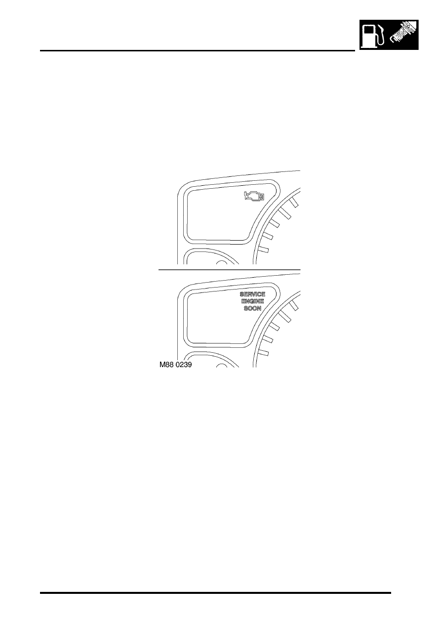
Malfunction Indicator Lamp (MIL)/ service engine soon warning lamp

The MIL/ service engine soon warning lamp is located in the instrument cluster. It illuminates to alert the driver to 
system malfunctions. Service engine soon warning lamp is the name for this warning lamp in NAS only, it is called 
MIL in all other markets. 

During ignition a self-test function of the lamp is carried out. The lamp will illuminate for 3 seconds then it will 
extinguish if no faults exist. 
 

 + 

 INSTRUMENTS, DESCRIPTION AND OPERATION, Description.

Input/Output
The MIL is supplied with battery voltage from the instrument cluster.  When the ECM detects a fault, it provides an 
earth path to illuminate the MIL. Output to the MIL is via pin 20 of connector C0637 of the ECM.

ENGINE MANAGEMENT SYSTEM - V8

18-2-40 DESCRIPTION AND OPERATION

Air Temperature Control (ATC) request
The ATC request comes via the ATC switch located in the facia panel. When the driver operates the switch it acts as 
a request from the ATC ECU to engage the ATC clutch to drive the system.

During periods of high driver demand such as hard acceleration or maximum rev/min the ATC clutch will be disabled 
for a short time. This is to reduce the load on the engine. 
 

 + 

 AIR CONDITIONING, DESCRIPTION AND OPERATION, Description.

Input/Output
The operation of the ATC request is via a switch being connected to earth. Voltage is supplied via pin 38 of connector 
C0637 of the ECM, at the point at when the switch is pressed the connection is made and the ATC clutch is engaged.

The ATC request can fail as follows:

l

Open circuit.

l

Short circuit to voltage supply.

l

Short circuit to vehicle earth.

l

Wiring loom fault.

In the event of an ATC request failure, the ATC system does not work.

Should a malfunction of the component occur the following fault codes may be evident and can be retrieved by 
TestBook.

ATC compressor clutch relay

The ATC compressor clutch relay is located in the engine compartment fuse box. It is a four pin normally open relay. 
The relay must be energised to drive the ATC compressor clutch.

P Code

J2012 Description

Land Rover Description

P1535

Air conditioning compressor request 
malfunction

ATC requested when not in standby mode

ENGINE MANAGEMENT SYSTEM - V8

DESCRIPTION AND OPERATION 18-2-41

Input/Output
The ECM provides the earth for the relay coil to allow the relay contacts to close and the ATC clutch drive to receive 
battery voltage. The ECM uses a transistor as a switch to generate an open circuit in the earth path of the relay coil.  
When the ECM opens the earth path, the return spring in the relay will pull the contacts apart to shut down the ATC 
clutch drive.

Input to the ATC clutch relay switching contacts is via fuse 6 located in the engine compartment fuse box. The relay 
coils are supplied with battery voltage from the main relay, also located in the engine compartment fuse box. The earth 
path for the relay coil is via pin 29 of the ECM C0657 connector. When the relay is energised the output from the 
switching contacts goes directly to the ATC compressor clutch.

The ATC clutch relay can fail in the following ways:

l

Relay open circuit.

l

Short circuit to vehicle supply.

l

Short circuit to vehicle earth.

l

Broken return spring.

In the event of an ATC clutch relay failure, the ATC does not work.

Should a malfunction of the component occur, the following fault codes may be evident and can be retrieved by 
TestBook.

P Code

J2012 Description

Land Rover Description

P1536

Air conditioning compressor request range/
performance

ATC compressor clutch relay open circuit

P1537

Air conditioning compressor request low input

ATC compressor clutch relay short to earth

P1538

Air conditioning compressor request high input

ATC compressor clutch relay short to battery supply

ENGINE MANAGEMENT SYSTEM - V8

18-2-42 DESCRIPTION AND OPERATION

Cooling fan relay

The cooling fan relay is located in the engine compartment fuse box. It is a four pin normally open relay. The relay 
must be energised to drive the cooling fan.

The cooling fan is used to cool both the condenser in which the ATC refrigerant is held and the radiator. This fan is 
used especially when the engine is operating at excessively high temperatures. It is also used as a part of the ECM 
backup strategy if the ECT fails.

Input/Output
The ECM provides the earth for the relay coils to allow the relay contacts to close and the cooling fan motor to receive 
battery voltage. The ECM uses a transistor as a switch to generate an open circuit in the earth path of the relay 
windings.  When the ECM opens the earth path, the return spring in the relay will pull the contacts apart to shut down 
the cooling fan motor drive.

Input to the cooling fan relay switching contacts is via fuse 5 located in the engine compartment fuse box. The relay 
coils are supplied with battery voltage from the main relay, also located in the engine compartment fuse box. The earth 
path for the relay coils is via pin 31 of the ECM connector C0636. When the relay is energised the output from the 
switching contacts is directly to the cooling fan motor.

The cooling fan relay can fail in the following ways:

l

Relay open circuit.

l

Short circuit to vehicle battery supply.

l

Short circuit to vehicle earth.

l

Broken return spring.

In the event of a cooling fan relay failure, the cooling fan does not work.


Content   ..  488  489  490  491   ..