Discovery 2. Manual - part 473


  Index      Land Rover     Land Rover Discovery 2 - service manual 1999 year


Search            


Content   ..  471  472  473  474   ..


Discovery 2. Manual - part 473


ENGINE MANAGEMENT SYSTEM - TD5

DESCRIPTION AND OPERATION 18-1-35

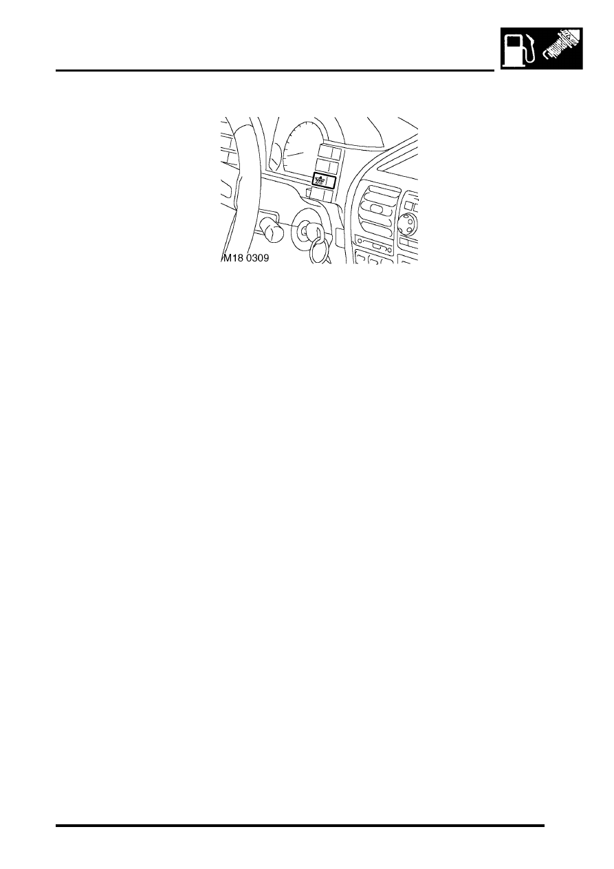
Cruise control master switch

The cruise control master switch is located on the dashboard. When the driver activates the switch it requests the 
cruise control system to be active. The switch acts as a latching switch, on the first operation of the switch the cruise 
control system is activated, when the switch is pressed again the cruise control system is de-activated. The cruise 
control warning lamp is part of the switch and illuminates when the switch is activated.

Input/Output
Input to the cruise control master switch is 12 volts via the main relay. When the switch is pressed the circuit is 
completed by the ECM providing an earth path for the relay via pin 15 of connector C0658 of the ECM.

The cruise control master switch can fail as follows:

l

Open circuit.

l

Short circuit to voltage supply.

l

Short circuit to vehicle earth.

l

Wiring loom fault.

In the event of a cruise control master switch failure cruise control does not operate.

ENGINE MANAGEMENT SYSTEM - TD5

18-1-36 DESCRIPTION AND OPERATION

Cruise control set/accelerate (SET+) switch

The cruise control SET+ switch is located on the vehicle steering wheel. The switch is a momentary switch and when 
pressed by the driver reacts as follows:

l

Requests the cruise control to become active and set at the current road speed if not already set.

l

If the cruise control is already set, pressing the switch increases the road speed at 1 mph (1.6 km/h) intervals.

The cruise control SET+ switch will only become active and operate under the following conditions:

l

The vehicle speed must be above 22 mph (35 km/h).

l

The cruise control master switch must be 'on'.

l

The brake pedal must not be pressed.

l

The automatic transmission must be in 'drive'.

l

The clutch pedal must not be pressed.

l

The suspend switch has not been operated.

Input/Output
Input to the cruise control SET+ switch is 12 volts via the main relay. When the switch is pressed the circuit is 
completed by the ECM providing an earth path for the relay via pin 11 of connector C0658 of the ECM.

The cruise control SET+ switch can fail as follows:

l

Open circuit.

l

Short circuit to voltage supply.

l

Short circuit to vehicle earth.

l

Wiring loom fault In the event of a cruise control SET+ switch failure cruise control does not operate.

Cruise control resume/suspend (RES) switch 
The cruise control RES switch is located on the vehicle steering wheel. The switch is a momentary switch and when 
pressed by the driver reacts as follows:

l

Requests the cruise control to be suspended if it has already been set.

l

Requests that cruise control is resumed at the previously set road speed.

The cruise control RES switch will only become active and operate under the following conditions:

l

The vehicle speed must be above 22 mph (35 km/h).

l

The cruise control master switch must be 'on'.

l

The brake pedal must not be pressed.

l

The automatic transmission must be in 'drive'.

l

The clutch pedal must not be pressed.

ENGINE MANAGEMENT SYSTEM - TD5

DESCRIPTION AND OPERATION 18-1-37

Input/Output
Input to the cruise control RES switch is 12 volts via the main relay. When the switch is pressed the circuit is completed 
by the ECM providing an earth path for the relay via pin 17 of connector C0658 of the ECM.

The cruise control RES switch can fail as follows:

l

Open circuit.

l

Short circuit to voltage supply.

l

Short circuit to vehicle earth.

l

Wiring loom fault.

In the event of a cruise control RES switch failure cruise control resume/ suspend operation does not operate.

ENGINE MANAGEMENT SYSTEM - TD5

18-1-38 DESCRIPTION AND OPERATION

Operation

Engine management
The ECM controls the operation of the engine using stored information within its memory. This guarantees optimum 
performance from the engine in terms of torque delivery, fuel consumption and exhaust emissions in all operating 
conditions, while still giving optimum driveability.

The ECM will receive information from its sensors under all operating conditions, especially during:

l

Cold starting.

l

Hot starting.

l

Idle.

l

Wide open throttle.

l

Acceleration.

l

Adaptive strategy.

l

Backup strategy for sensor failures.

The ECM receives information from various sensors to determine the current operating state of the engine. The ECM 
then refers this information to stored values in its memory and makes any necessary changes to optimise air/fuel 
mixture and fuel injection timing. The ECM controls the air/fuel mixture and fuel injection timing via the Electronic Unit 
Injectors (EUI), by the length of time the EUI's are to inject fuel into the cylinder.  This is a rolling process and is called 
adaptive strategy. By using this adaptive strategy the ECM is able to control the engine to give optimum driveability 
under all operating conditions.

During cold start conditions the ECM uses ECT information to allow more fuel to be injected into the cylinders, this 
combined with the glow plug timing strategy supplied by the ECM facilitates good cold starting.

During hot start conditions the ECM uses ECT and FT information to implement the optimum fuelling strategy to 
facilitate good hot starting.

During idle and wide open throttle conditions the ECM uses mapped information within its memory to respond to input 
information from the throttle pedal position sensor to implement the optimum fuelling strategy to facilitate idle and wide 
open throttle.

To achieve an adaptive strategy for acceleration the ECM uses input information from the CKP sensor, TP sensor, 
ECT sensor, MAP/ IAT sensor, and the FT sensor. This is compared to mapped information within its memory to 
implement the optimum fuelling strategy to facilitate acceleration. 

Immobilisation system
When the starter switch is turned on, the BCU sends a unique security code to the ECM. The ECM must accept this 
code before it will allow the engine to operate. If the ECM receives no security code or the ECM receives the incorrect 
security code, then the ECM allows the engine to run for 0.5 seconds only. During this operation all other ECM 
functions remain as normal.

The ECM operates immobilisation in three states:

l

'New.'

l

'Secure'.

l

'No Code'.

When an ECM is unconfigured it will operate in the 'New' state. When an unconfigured ECM is installed the engine 
can be started and operated once only, then the ECM has to be re-configured to either 'secure' or 'no code' 
configuration depending on whether a security system is fitted to the vehicle. This is achieved by using TestBook.


Content   ..  471  472  473  474   ..