Discovery 2. Manual - part 420


  Index      Land Rover     Land Rover Discovery 2 - service manual 1999 year


Search            


Content   ..  418  419  420  421   ..


Discovery 2. Manual - part 420


ENGINE - TD5

OVERHAUL 12-1-77

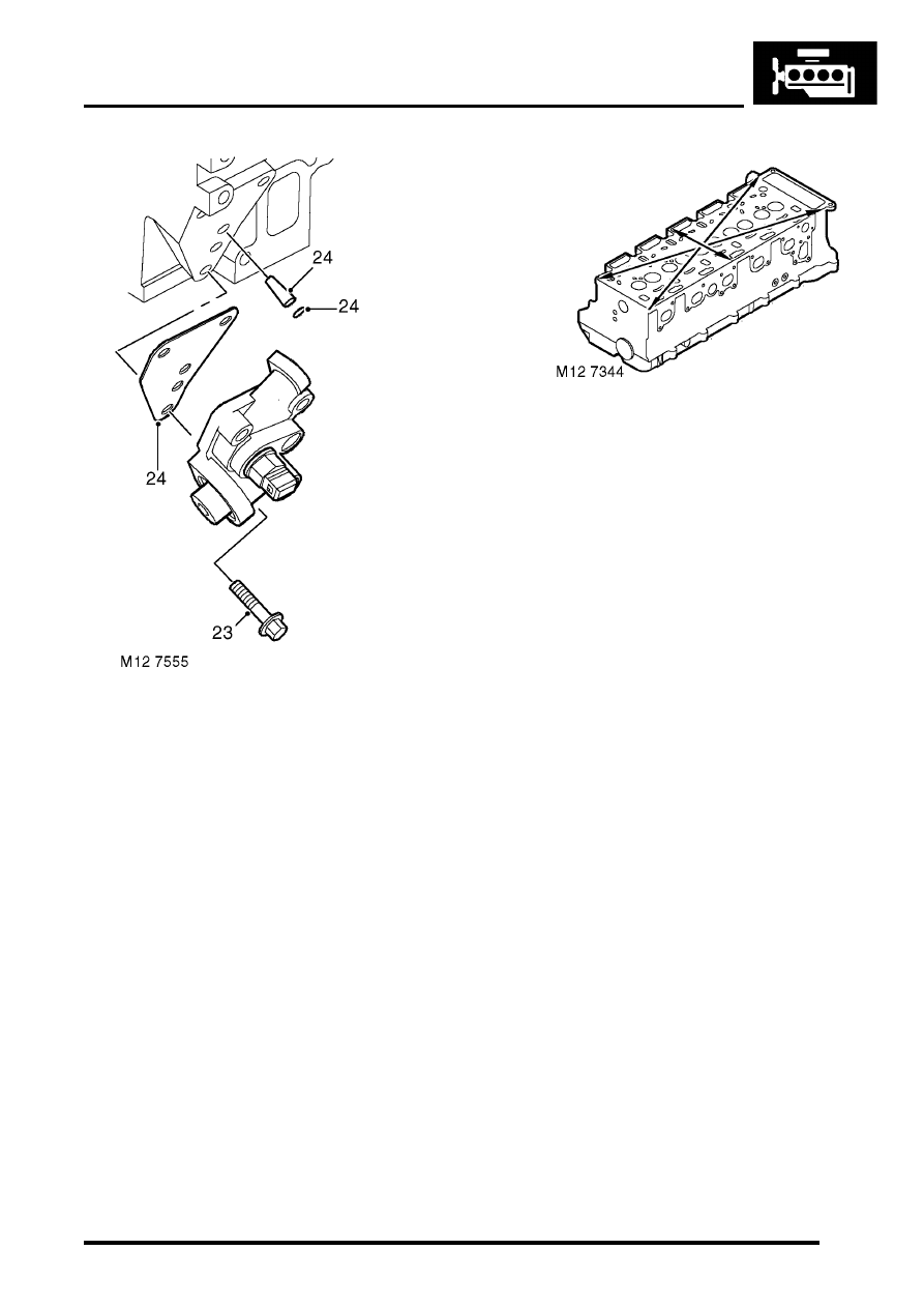
23. Remove 3 bolts and remove fuel connector 

block from cylinder head. 

24. Remove gasket, discard 'O' ring and fuel filter. 
25. If fitted:  Remove spacer block and gasket.

Inspect

1. Thoroughly clean cylinder head mating faces, 

ensure that EUI  drillings, oil and coolant 
passages are clear and bolt holes are  clean 
and dry.

2. Using suitable solvent, remove all traces of 

sealant and gasket  material.

CAUTION: Do not use metal scrapers.

3. Remove all traces of oil from camshaft bearings 

and journals.

4. Clean glow plug threads.
5. Check core plugs for signs of leakage and 

corrosion, seal  replacement plugs with  Loctite 
243.

6. Check cylinder head for warping across centre 

and from corner  to corner:

l

 Maximum cylinder head warp = 0.1 mm  
(0.004 in)

Cylinder heads must not be refaced. 

Replace the head  assembly if warping 
exceeds the limit.

7. Check lash adjuster bores for scoring and signs 

of wear or damage. 

8. Check lash adjusters for signs of wear, scoring 

and overheating,  replace as necessary. 
Ensure oil hole in each lash adjuster is clear.  
Store lash adjusters upright and in their 
fitted order.

9. Check finger followers for wear and that rollers 

are free to  rotate.  Store finger followers in  
their fitted order.

10. Check camshaft lobes and bearing journals for 

signs of scoring  and wear. 

11. Check bearing surfaces in cylinder head and 

camshaft carrier  for signs of scoring and wear. 

Cylinder head and camshaft carrier are 
machined together as an assembly. If 
bearing surfaces in either component are 
damaged,  both components must be 
replaced as an assembly.

12. Check camshaft end-float using following 

procedures.

13. Position camshaft in camshaft carrier. 

ENGINE - TD5

12-1-78 OVERHAUL

14. Check end-float of camshaft using a DTI:

l

 Camshaft end-float = 0.06 to 0.16 mm 
(0.002 to 0.006 in)

15. Renew components as necessary to achieve 

correct end-float.

16. Check camshaft bearing clearances using the 

following procedures.

17. Position camshaft in cylinder head.
18. Place a piece of Plastigage along centre line of 

each camshaft  bearing journal.

19. Carefully fit the camshaft carrier ensuring it is 

located on  dowels. Do not rotate camshaft.

20. Fit original camshaft carrier bolts and tighten  in 

sequence  shown to 25 Nm (18 lbf.ft).

21. Using sequence shown, loosen then remove 

camshaft carrier  retaining bolts. Do not 
discard bolts at this  stage.

22. Carefully remove camshaft carrier. 

23. Measure and record widest portion of 

Plastigage on each camshaft  bearing journal.

ENGINE - TD5

OVERHAUL 12-1-79

24. Compare figures obtained with camshaft 

bearing clearance:   

l

Camshaft bearing clearance =  0.04 to 0.10 
mm (0.002 to 0.004 in)

25. If any bearing clearance is found to exceed 

figures given, repeat  the above procedures 
using a new camshaft. If, after repeating the  
clearance check using a new camshaft the 
clearances are still  excessive, a new cylinder 
head and camshaft carrier assembly must be  
fitted.

26. Remove all traces of Plastigage using an oily 

cloth, do not  use a scraper.

27. On completion, discard camshaft carrier bolts.
28. Check free length of valve springs:

l

Free length = 46.75 to 47.25 mm (1.84 to 
1.86 in)

29. Replace valve springs as a set, if springs 

are to be refitted,  keep them in their fitted 
order.

30. Clean carbon from valves, check valves for 

burning, pitting or  cracking; replace as 
necessary.

31. Clean carbon from valve seat inserts, remove 

all loose particles  on completion.

32. Check valve seat inserts for pitting and burning.  

It is not permissible to recut or replace valve  
seat inserts. 

33. Remove carbon deposits from valve guides 

using tool   LRT-12-186 inserted  from the 
combustion chamber face side of cylinder 
head. Ensure all  loose particles of carbon are 
removed on completion. 

34. Check and record diameter of each valve stem:   

l

Valve stem diameter - Inlet = 6.907 to 6.923 
mm  (0.2719 to 0.2725 in)                                            

l

Valve stem diameter - Exhaust = 6.897 to 
6.913 mm  (0.2715 to 0.2721 in)

35. Renew any valve if stem diameter is less than 

specified.

36. Check and record valve stem to guide 

clearance using the  following procedures.

37. Insert each valve into its respective guide.
38. Extend valve head 10 mm (0.375 in) out of 

valve seat and  position a DTI gauge to rear of 
valve head.

39. Move valve towards front of cylinder head and 

zero DTI gauge  ensuring that stylus of gauge 
remains in contact with valve head.

40. Move valve towards rear of cylinder head, 

record gauge reading  to give valve stem to 
guide clearance:   

l

Inlet valve = 0.025 to 0.059 mm (0.0009 to 
0.0023 in)

l

Exhaust valve = 0.035 to 0.069 mm (0.0013 
to 0.0027 in)

41. If stem to guide clearance exceeds figures 

given  and valve stem diameters were as 
specified, cylinder head assembly must  be 
replaced; it is not possible to replace valve 
guides.

42. Repeat above procedures for remaining valves.  

Keep valves in their fitted order.

43. Check face angle of each valve, renew any 

valve with incorrect  face angles, do not attempt 
to recut.

l

Valve face angle - inlet = 29

°

 48' 

±

 12'

l

Valve face angle - exhaust  = 44

°

 48' 

±

 12'

44. Lap each valve to its seat using grinding paste.
45. Apply Prussion Blue to valve seat, insert valve 

into guide and  press it firmly, without rotating 
on to seat.

46. Remove valve and check that a continuous, 

even line of Prussian  Blue has been 
transferred on to valve face.   Note that line 
does not have to be across whole  width of 
valve face. 

47. Remove all traces of grinding paste on 

completion.

48. Check valve head stand down using the 

following procedures.

ENGINE - TD5

12-1-80 OVERHAUL

49. Insert each valve into its respective guide.
50. Using a straight edge and feeler gauges, check 

and record  stand down of each valve head.

51. Compare figures obtained with those given 

below:

l

Valve head stand down - Inlet valve A = 
0.555 to 0.825 mm  (0.022 to 0.032 in) 

l

Valve head stand down - Exhaust valve B = 
0.545 to 1.35 mm  (0.021 to 0.053 in)

52. If any valve has a stand down greater than 

specified,  repeat check using a new valve. 
If, after checking with a new valve,  stand 
down is still excessive, cylinder head 
assembly must be replaced.  It is not 
possible to replace valve seat inserts.

53. Suitably identify each rocker arm to its fitted 

position and type of rocker arm fitted. 

NOTE:

l

Engine Serial No. Prefixes 10P to 14P - 
Type A rocker arms

l

Engine Serial No. Prefixes 15P to 19P - 
Type B rocker arms. 

Type B rocker arms and shafts may be fitted to 
Engine Serial No. Prefixes 10P to 14P as an 
assembly.


Content   ..  418  419  420  421   ..