Discovery 2. Manual - part 407


  Index      Land Rover     Land Rover Discovery 2 - service manual 1999 year


Search            


Content   ..  405  406  407  408   ..


Discovery 2. Manual - part 407


ENGINE - TD5

DESCRIPTION AND OPERATION 12-1-25

Inlet and exhaust valves
The inlet and exhaust valves are mounted directly above the engine block cylinders.

Each valve is a forged and ground solid one-piece head and stem which is hardened by heat treatment. The stems 
are chrome-plated then ground for improved heat transfer, wear resistance and smooth operation.  It is not possible 
to recut the valve's face angle, but the valves can be lapped to their seats using grinding paste.

The valve springs are made from spring steel and are of the parallel single-coil type. The bottom end of the spring 
rests on the flange of a spring seal which has a centre bore that locates on a recess ground into the lower valve stem. 
The top end of the spring is held in place by a spring retainer which is held in position at the top end of the valve stem 
by split taper collets. The taper collets have grooves on the internal bore that locate to grooves ground into the upper 
stems of the valves.

The valve seats and valve guides are sintered and are interference fit into the cylinder head. The valve seats and 
guides are non-serviceable.

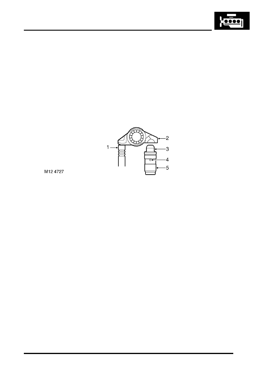
Finger followers and Lash adjusters

Valve stem
Finger follower
Lash adjuster plunger
Oil supply hole
Lash adjuster body

The valves are operated through finger followers and lash adjusters, actuated by the camshaft lobes. When the 
camshaft lobe presses down on the top of a finger follower roller mechanism, the respective valve is forced down 
opening the effected inlet or exhaust port.

The lash adjuster body contains a plunger and two chambers for oil feed and pressurised oil. Pressurised oil is 
supplied to the lash adjusters via the oil galleries in the cylinder head and through a hole in the side of the lash adjuster 
body. The oil passes into a feed chamber in the lash adjuster then through to a separate pressure chamber via a one 
way ball valve. Oil flow from the pressure chamber is determined by the amount of clearance between the lash 
adjuster outer body and the centre plunger, oil escapes up the side of the plunger every time the lash adjuster is 
operated, the downward pressure on the plunger forcing a corresponding amount of oil in the lash adjuster body to 
be displaced. When the downward pressure from the camshaft and finger follower is removed (i.e. after the trailing 
flank of the camshaft lobe has passed), oil pressure forces the lash adjuster's plunger up again. This pressure is not 
sufficient to affect the valve operation, but eliminates the clearance between the finger follower and top of the valve 
stem.  

ENGINE - TD5

12-1-26 DESCRIPTION AND OPERATION

Camshaft cover and engine cover components
The camshaft cover and engine cover components are described below:

Camshaft cover
The camshaft cover is cast from aluminium alloy and is fixed to the camshaft carrier/cylinder head assembly by 13 
bolts. The cover has spacers and sealing washers inserted into each of the thirteen bolt holes. 

A breather hose is connected to a port at the top of the camshaft cover by means of a hose clip which vents crankcase 
gases back to the air intake via a breather valve in the air intake tract, located forward of the turbocharger in the 
flexible air intake duct.

A rubber seal is fitted between the camshaft cover.

An oil filler aperture is included in the top of the camshaft cover, which is sealed with a plastic cap with integral rubber 
seal.

Camshaft timing chain components
The timing chain cover and timing chain components are described below:

Timing chain cover
The timing chain cover is cast and machined aluminium alloy and is attached to the cylinder head by a bolt at the RH 
top of the cover and by a stud and nut at the LH top of the cover. Eight screws are used to attach the timing chain 
cover to the front of the engine block. The timing cover is located to the cylinder block front face by two dowels.

A viscous fan is attached to an idler pulley at the front of the engine block. The fan bearing is located on a shaft and 
held in place by a circlip and a bearing flange, the inner race of the fan bearing is an interference fit on the shaft. The 
fan idler pulley is attached to the bearing hub by three bolts, and the fan itself is secured to the pulley and bearing 
shaft by a left hand threaded nut.
 

 + 

 COOLING SYSTEM - Td5, DESCRIPTION AND OPERATION, Description.

The front of the crankshaft passes through a hole in the lower part of the timing cover. An oil seal is pressed into a 
recess in the front of the timing cover to seal the interface between the front of the crankshaft and the timing cover.

A stub pipe is fitted to the front RH side of the timing cover which is used to attach the oil drain pipe from the vacuum 
pump by means of a hose and spring clip.

Timing chains
The timing chain between the camshaft and crankshaft sprockets is a duplex type, each chain having 56 links. The 
timing chain is contained between a fixed plastic guide and an hydraulically adjustable plastic tensioner arm which 
are attached to the front of the engine block.

To cope with higher injection loads of the EU3 engine, the timing drive between the camshaft and crankshaft has been 
upgraded. This requires thicker chain links to be used, therefore, the individual pre EU3 and EU3 components are not 
interchangeable.

To distinguish between the two timing chains the links are different colours. A pre EU3 chain has blue links and a EU3 
chain has bronze links.

The oil pump timing chain is a single type and traverses the oil pump sprocket and the rear crankshaft sprocket.

The timing chains are oil lubricated, with oil being provided by a chain lubrication jet and from oil flow returning back 
to the sump from the cylinder head. An oil hole is included at the front left hand side of the cylinder head which supplies 
oil from the cylinder head oil galleries.

ENGINE - TD5

DESCRIPTION AND OPERATION 12-1-27

Timing chain guides

Hydraulic tensioner
Adjustable tensioner arm
Duplex timing chain
Camshaft sprocket
Fixed tensioner arm
Crankshaft sprocket

The crankshaft sprocket to camshaft sprocket timing chain is held taut by a tensioner arm acting on the slack side of 
the chain. The tensioner is automatically adjusted by means of an hydraulically operated tensioner adjuster. The drive 
side of the chain has a  plastic guide attached to the front face of the cylinder block. The fixed guide is attached to the 
front of the engine block by two bolts. The tensioner arm is fixed to the front of the cylinder block by a single pivot bolt 
which allows the tensioner arm to pivot about its axis.

The adjustable tensioner arm is not interchangeable between pre EU3 and EU3 models due to a change in geometry 
on the EU3 version.

ENGINE - TD5

12-1-28 DESCRIPTION AND OPERATION

Tensioner adjuster

Oil supply hole
Tensioner adjuster body
Tensioner adjuster plunger
Sealing ring

The tensioner adjuster is hydraulically operated, oil enters the adjuster from the pressurised oil supply flowing through 
the cylinder head to operate a plunger which pushes against a pivoting plastic tensioner arm. The lateral movement 
in the tensioner arm causes the timing chain to tension and consequently compensation for chain flutter and timing 
chain wear is automatically controlled. The adjuster is located at the front right hand side of the cylinder head, just 
above the timing chain cover and below the vacuum pump oil feed port. The adjuster body is threaded and screws 
into a tapping in the cylinder head. Holes are contained in the adjuster body to receive oil from the cylinder head 
galleries, the oil pressure is used to force the plunger out of the adjuster body to press the tensioner arm against the 
timing chain and so using the oil trapped in the adjuster body to perform as a damper.

The internal damping of the hydraulic tensioner is tuned for each application. This means that pre EU3 and EU3 
components are not interchangeable.

Drive train sprockets
The camshaft sprocket has a double row of teeth which locate with the duplex timing chain. The sprocket is fitted to 
the camshaft by three bolts.

The oil pump sprocket is located on the front of the oil pump housing by a single retaining bolt. The sprocket has a 
single row of teeth which locates on the oil pump chain.

The crankshaft sprocket contains three rows of teeth, the rear row locates on the single oil pump chain and the front 
two rows locate with the duplex timing chain. The crankshaft sprocket has a slot in its internal diameter which locates 
with the Woodruff key on the crankshaft. The front of the crankshaft sprocket has a timing mark.

As a consequence of thicker chain links being used on EU3 models, the thickness of the camshaft and crankshaft 
sprocket teeth has been reduced. Individual pre EU3 and EU3 components are therefore not interchangeable.


Content   ..  405  406  407  408   ..