Discovery 2. Manual - part 404


  Index      Land Rover     Land Rover Discovery 2 - service manual 1999 year


Search            


Content   ..  402  403  404  405   ..


Discovery 2. Manual - part 404


ENGINE - TD5

DESCRIPTION AND OPERATION 12-1-13

Two plastic dowels are used to locate the cylinder head to the cylinder block and must be replaced every time the 
cylinder head is removed from the cylinder block.
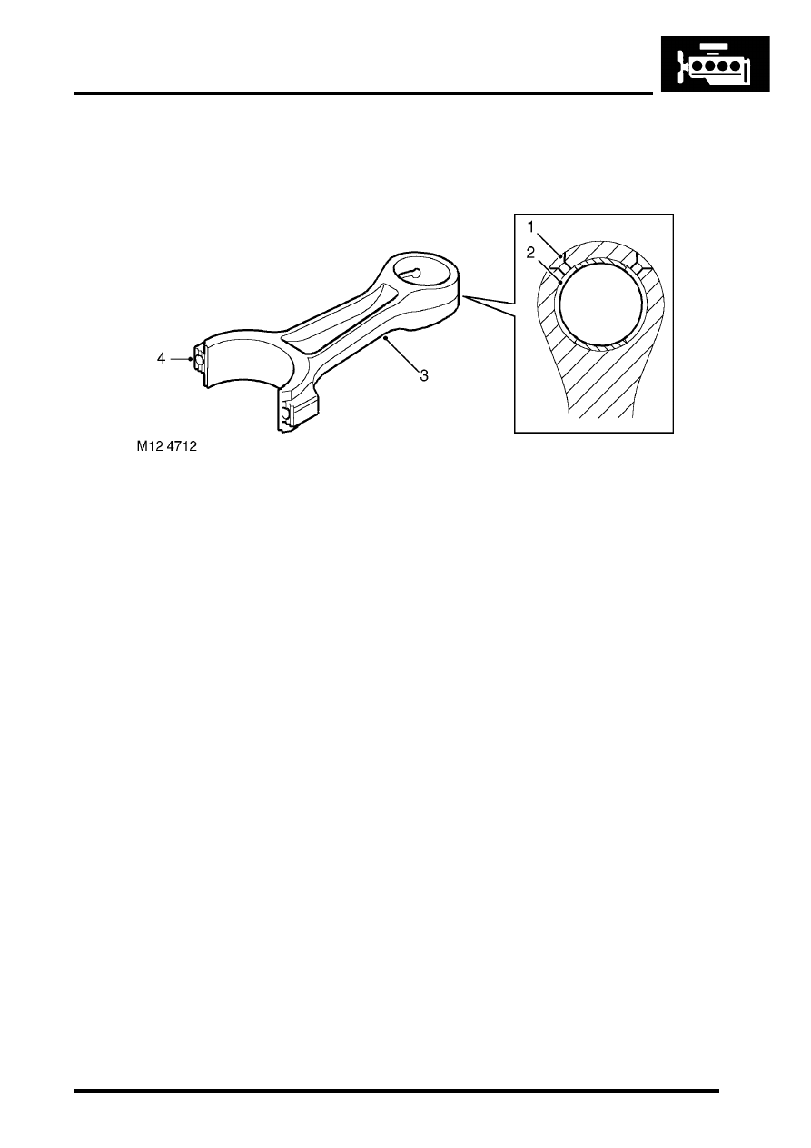
Connecting rods

Small-end oil holes
Small-end bushing
Connecting rod
Serrated fracture

The connecting rods are machined, H-sectioned steel forgings which feature a fracture-split at the big-end between 
the connecting rod and the bearing cap. The connecting rod features a serrated fracture across the big-end at right 
angles to the length of the connecting rod, this forms a unique mating surface between the connecting rod and the 
fractured end which is used as the big-end cap. The use of a fracture-split in the big-end of the connecting rod ensures 
a perfect match for assembly on the crankshaft bearing journals and provides the connecting rod with strong 
resistance to lateral movement.

The end-cap fixing bolts are offset to ensure that the cap is fitted to the connecting rod in the correct orientation. If the 
end-cap is fitted incorrectly and the end-cap bolts tightened, the connecting rod must be replaced, since the matching 
serrations will have been damaged.

The big-end bearing shells are plain split halves without location tags. On EU2 models the two halves of the bearing 
shells are of different construction. The upper half bearing shell fitted to the connecting rod is treated using the 
sputtering process. The connecting rod bearing shell can be identified by having a slightly darker colouration than the 
end cap bearing shell and the back of the connecting rod bearing shell has a shinier finish than the front face.

On EU3 models both bearing shells are of the same construction as the connecting rod bearing shell.

The small-end of the connecting rod has a bushed solid eye which is free to move on the gudgeon pin, the bushing 
is a hand-push interference fit. The steel bushing has two slots machined in its upper surface for providing oil 
lubrication to the moving surface with the gudgeon pin. The oil slots must be correctly aligned to the oil slots provided 
in the small end of the connecting rod. The small-end lubrication is supplied by squirt feed from the piston lubrication 
jets.

ENGINE - TD5

12-1-14 DESCRIPTION AND OPERATION

Pistons

Bowl in piston head
Piston ring grooves
Graphite coated aluminium alloy skirt
Gudgeon pin bore

The five pistons have graphite-compound coated aluminium alloy skirts which are gravity die cast and machined. 
Each of the pistons has phosphated, shaped gudgeon pin bores and a swirl chamber (bowl-in-piston) machined in the 
head which partly contains the inlet air that is compressed during the combustion process and helps provide 
turbulence for efficient air/fuel mixture to promote complete combustion. The recesses in the piston's crown also 
provide clearance for the valve heads.

Pre EU3 and EU3 pistons are not interchangeable due to the EU3 piston combustion bowl being offset.

The pistons are attached to the small-end of the connecting rods by fully floating gudgeon pins which are retained in 
the piston gudgeon pin bushings by circlips.

The pistons and gudgeon pins are gallery cooled, oil being supplied under pressure from the piston lubrication jets 
when the pistons are close to bottom dead centre.

Piston rings
Each piston is fitted with two compression rings and an oil control ring. The top compression ring is located in a steel 
insert ring carrier which helps to provide a minimal reaction to compression forces.

The top ring is barrel-edged and chrome-plated, the 2nd compression ring is taper-faced and the oil control ring is 
chrome-plated and features a bevelled ring with spring.

ENGINE - TD5

DESCRIPTION AND OPERATION 12-1-15

Oil cooler

Front oil gallery – full-flow filter to oil cooler 

matrix

Full-flow filter adaptor outlet port to oil cooler 

(open at >74

°

 C)

Full-flow filter inlet port
Oil cooler housing
Full-flow filter outlet port to cylinder block
Coolant inlet port
Oil cooler banjo bolt seals (2 off)
Banjo bolts (2 off)
Banjo bolt oil holes – to oil cooler matrix

10 Rear oil gallery – full-flow filter/oil cooler outlet 

to cylinder block

11 Centre oil gallery – from pump to full-flow filter
12 Inlet port to centrifuge filter
13 Sealing ring – centrifuge filter housing to oil 

cooler housing

14 Port – oil cooler matrix
15 Oil cooler matrix
16 Inlet port from pump via cylinder block to oil 

cooler housing

17 Outlet port from oil cooler housing to cylinder 

block

18 Rear view of oil cooler housing

The engine oil cooler assembly is located on the left hand side of the engine block behind the oil centrifuge and oil 
filter. The housing is bolted to the engine block by seven bolts. A matrix is included in the oil cooler housing which 
acts as a heat exchanger. Coolant flow circulates through the oil cooler housing under pressure from the coolant pump 
and distributes the flow evenly around the matrix fins and then along the block into three core holes for cylinder 
cooling. Coolant enters the oil cooler through a pipe with a rubber hose extension at the rear side of the engine. The 
coolant hose is attached to the stub pipe of the oil cooler by a spring clip.

Oil drawn from the sump by the oil pump passes through the oil cooler via the cylinder block. The flow of coolant 
around the exterior surface of the oil cooler matrix cools a proportion of the engine oil flow as it passes through the 
oil cooler matrix.

The oil cooler is sealed to the cylinder block by a gasket which must be replaced every time the oil cooler housing is 
removed.

ENGINE - TD5

12-1-16 DESCRIPTION AND OPERATION

Oil filters
The Td5 engine features two types of oil filter; the main filter is a  standard disposable cartridge-type full-flow oil filter 
which is augmented with a by-pass centrifuge filter used to filter out particulate matter having a diameter smaller than 
15 micron but greater than 3 micron.

Centre spindle
Spindle oil holes (2 off)
Centrifuge filter housing
Centrifuge filter drain pipe
Port – centrifuge filter drain pipe to sump

Filter rotor
Internal seal
Cover
Cover bolts (2 off)

The centrifuge filter is located on the left hand side of the engine block by the exhaust manifold and is housed in a pot 
which is bolted to the oil cooler housing by means of three bolts. The pot contains a rotor located on a central spindle 
which spins at up to 15,000 revs/min. when oil is flowing through the unit under pressure. The rotor contains two fine 
holes drilled at obtuse angles which cause the rotor to spin about the centre spindle when high pressure oil is passing 
through it. The inner surface of the rotor captures carbon deposits and small particulate matter as it is thrown outwards 
under centrifugal force to form a sludge on the inner walls of the rotor. The unit is able to trap very fine impurities that 
build up in the oil that would be too small to filter using the normal paper-element type full-flow filters alone.

Approximately 10% of the total oil flow enters the centrifuge pot through a side port in the pot casting which is mated 
to an outlet port at the lower side of the oil cooler housing. A rubber O-ring sits in a recess around the oil cooler port 
which seals the faces between the centrifuge pot and oil cooler port, and it must be replaced every time the centrifuge 
assembly is removed. Oil leaves the centrifuge pot through a drain tube which is attached to the base of the pot by 
means of two fixing screws. The lower end of the drain tube returns oil to the sump and is fixed to the sump by means 
of two screws. Gaskets are included at the port interfaces between the oil drain tube and the centrifuge pot, and the 
oil drain tube and sump return port; these gaskets must be replaced every time the oil drain tube is removed.

The centrifuge cover is fixed to the pot by two screws and is sealed by an 'O'-ring. 


Content   ..  402  403  404  405   ..