Discovery 2. Manual - part 360
NAVIGATION SYSTEM
DESCRIPTION AND OPERATION
87-15
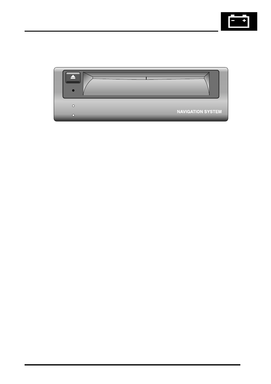
Navigation Computer
The Navigation computer is delivered pre-loaded with operating software, 2 languages and the Off Road navigation
software. The 2 pre-loaded languages are:
l
UK English (Female)
l
German (Male)
Software loading can be achieved at any time by inserting a software CD into the CD-ROM drive. The navigation
computer compares the version of software on the CD with that currently loaded. If the software version on the CD is
a later version it automatically loads the new software. The status of software loading is shown on the display unit.
On completion of software loading, the CD is automatically ejected. The user is prompted to remove the CD and
confirm. The computer then resets and restarts with the new software.
M86 6061
ON
CD-IN