Discovery 2. Manual - part 340


  Index      Land Rover     Land Rover Discovery 2 - service manual 1999 year


Search            


Content   ..  338  339  340  341   ..


Discovery 2. Manual - part 340


IN CAR ENTERTAINMENT

DESCRIPTION AND OPERATION 86-6-21
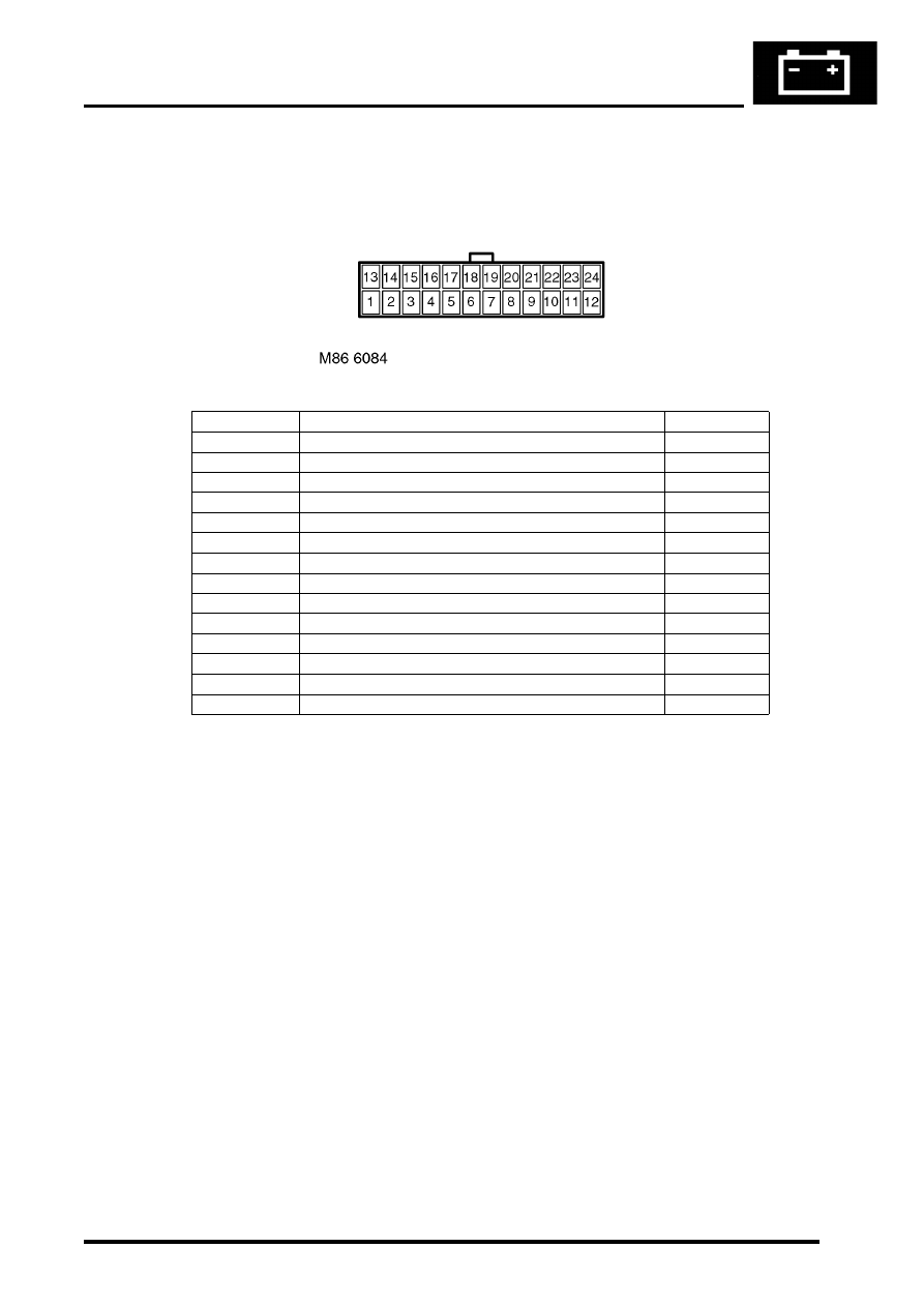
Connector C01
Connector C01 is located on the overhead console and transmits signals between the overhead console and the CD 
switch.

Pin No.

Description

Input/Output

1

Shield ground

Input

2

Audio Left from console to CD switch

Output

3

Audio return from console to CD switch

Output

4

Audio right from console to CD switch

Output

10

Signal ground

Input

11

Vehicle data 1 from console to CD switch

Input/Output

12 – 13

Not used

14

Vehicle data 4 – Connected to pin 10

Input

15

Vehicle data 5 – Connected to pin 10

Input

16

Vehicle data 6 – Data from console to CD switch

Input/Output

17 – 21

Not used

22

Accessory power from CD switch to console

Input/Output

23

Battery power from CD switch to console

Input

24

Power ground from CD switch to console

Input

IN CAR ENTERTAINMENT

86-6-22 DESCRIPTION AND OPERATION

Connector C04
Connector C04 is located on the CD switch and transmits signals between the CD switch and the overhead console.

Pin No.

Description

Input/Output

1

Shield ground

Input

2

Audio left from console to CD switch

Input

3

Audio return from console to CD switch

Input

4

Audio right from console to CD switch

Input

5

Vehicle data 5 – Connected from console to CD switch

Input/Output

6

Vehicle data 1 – Connected between console and CD switch

Input/Output

7

Vehicle data 6 – Connected between console and CD switch

Input/Output

8

Accessory power from CD switch to console

Input 12V

9

Battery power from CD switch to console

Input 12V

10

Power ground from CD switch to console

Input

IN CAR ENTERTAINMENT

DESCRIPTION AND OPERATION 86-6-23

Connector C07
Connector C07 is located on the CD switch and transmits signals between the CD switch and the CD autochanger 
and the audio head unit.

Pin No.

Description

Input/Output

1

Not used

2

I Bus data connection between CD switch and head unit

Input/Output

3

Audio left + from CD switch to head unit

Output

4

Audio left – from CD switch to head unit

Output

5

Audio right + from CD switch to head unit

Output

6

Audio right – from CD switch to head unit

Output

7

I Bus data connection between CD switch and CD autochanger

Input/Output

8

Audio left + from CD autochanger to CD switch

Output

9

Audio left – from CD autochanger to CD switch

Output

10

Audio right + from CD autochanger to CD switch

Output

11

Audio right – from CD autochanger to CD switch

Output

12 – 13

Not used

14

Power ground from passenger compartment fusebox to CD switch

Input

IN CAR ENTERTAINMENT

86-6-24 DESCRIPTION AND OPERATION

Connector C08
Connector C08 is located in the harness from the CD autochanger to the CD switch.

Pin No.

Description

Input/Output

1

Audio right + from CD autochanger to CD switch

Input

2

Audio right – from CD autochanger to CD switch

Input

3 – 4

Not used

5

I Bus data connection between CD autochanger and CD switch

Input/Output

6

Audio left + from CD autochanger to CD switch

Input

7

Audio left – from CD autochanger to CD switch

Input

8

Power ground from head unit to CD autochanger

Input

9

Not used

10

Battery power from head unit to CD autochanger

Input


Content   ..  338  339  340  341   ..