Discovery 2. Manual - part 284
HEATING AND VENTILATION
DESCRIPTION AND OPERATION
80-7
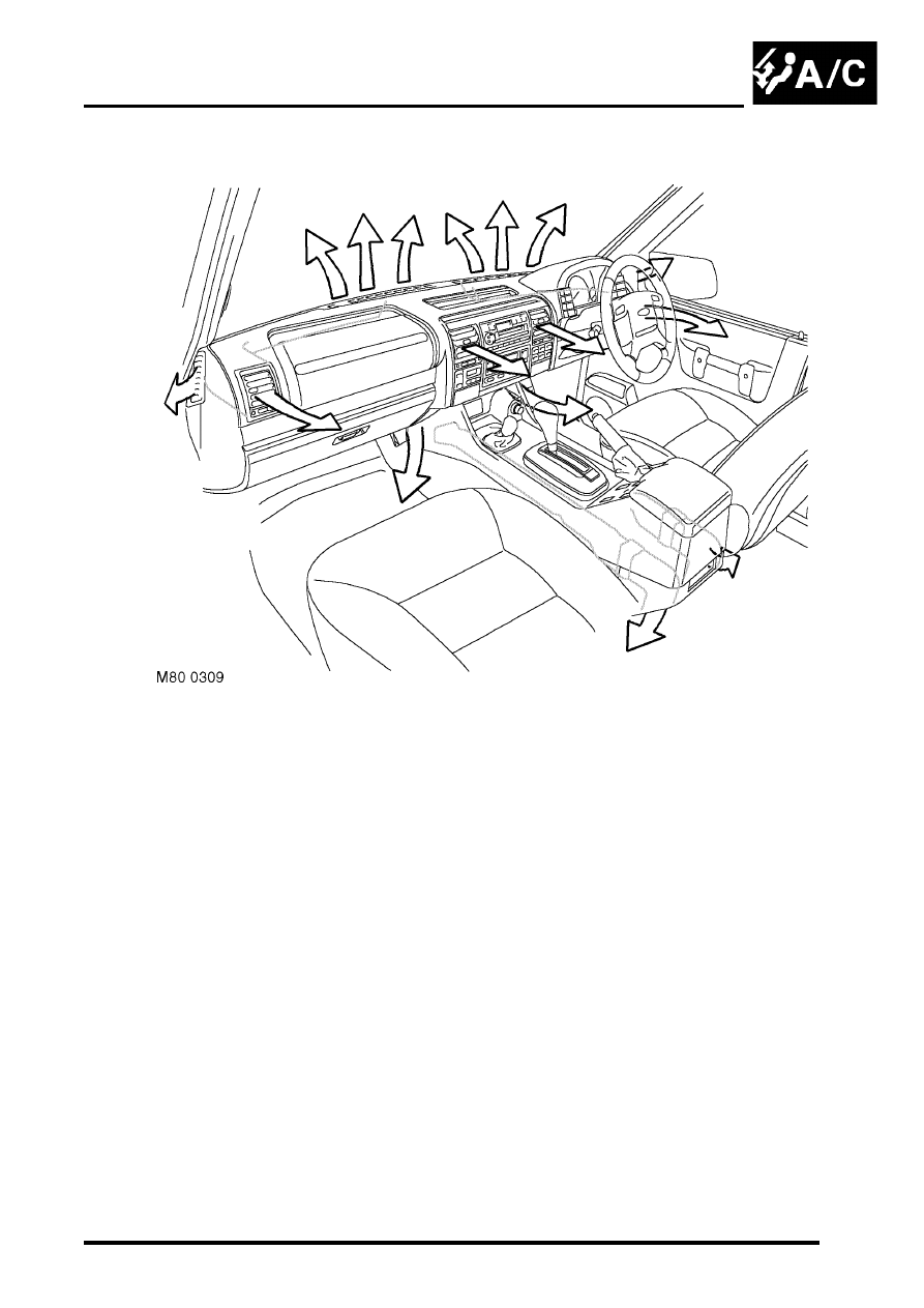
Distribution ducts
Separate distribution ducts are installed for the front and rear footwell outlets. Distribution ducts for the face level,
windscreen and side windows outlets are integrated into the fascia. The front footwell ducts are attached to ports at
the sides of the heater assembly. The rear footwell ducts locate in ports at the rear of the heater assembly and extend
along each side of the centre console to vent into the rear footwells from below the cubby box.
Vent assemblies in the fascia allow occupants to control the flow and direction of face level air. Each vent assembly
incorporates a thumbwheel to regulate flow and moveable vanes to control direction.