Discovery 2. Manual - part 186


  Index      Land Rover     Land Rover Discovery 2 - service manual 1999 year


Search            


Content   ..  184  185  186  187   ..


Discovery 2. Manual - part 186


FRONT SUSPENSION

REPAIRS

60-27

REPAIRS

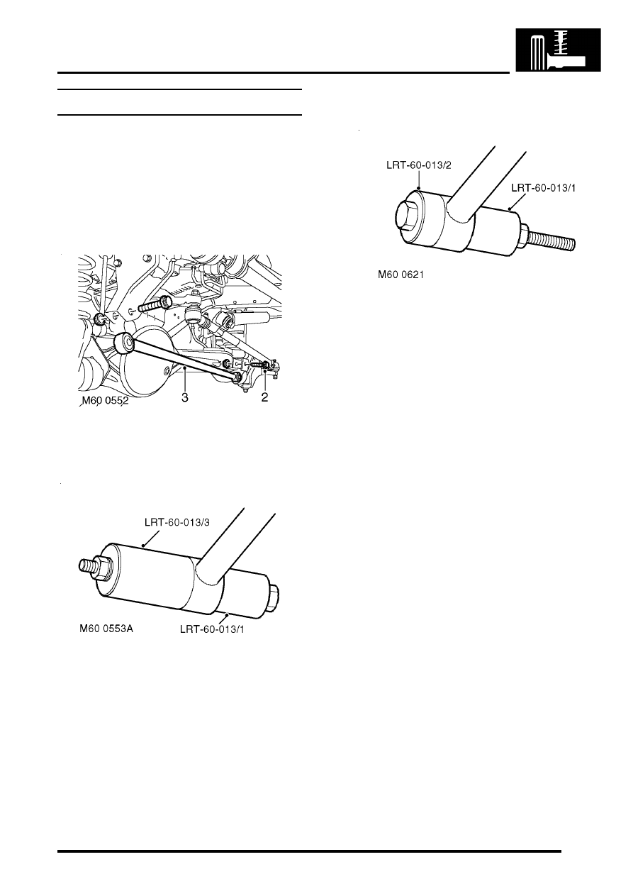
Bushes - Panhard rod  

$% 60.10.07 

Remove

1. Raise front of vehicle. 

WARNING: Do not work on or under a 
vehicle supported only by a jack. Always 
support the vehicle on safety stands.

2. Remove 2 nuts and bolts securing Panhard  rod 

to axle and chassis. 

3. Remove Panhard rod from vehicle. 

4. Use tool LRT-60-013  fitted with LRT-60-013/1  

and  LRT-60-013/3  to press out bushes from 
Panhard rod. 

Refit

1. Clean bush locations in Panhard rod. 

2. Use tool LRT-60-013 fitted with  LRT-60-013/1  

and LRT-60-013/2  to press new bushes into 
Panhard rod. Ensure pressure is applied to 
the outer edge of the bush, not the rubber 
inner. 

3. Position Panhard rod to axle and chassis. 
4. Fit bolts securing Panhard rod but do not 

tighten at this stage.

5. Remove stand(s) and lower vehicle.
6. Tighten bolts securing Panhard rod  to 230 Nm 

(170 lbf.ft). 

CAUTION: Nuts and bolts must be tightened 
with weight of vehicle on suspension.

FRONT SUSPENSION

60-28

REPAIRS

Ball joint - upper - steering knuckle  

$% 60.15.02  

CAUTION: Each ball joint can be replaced up to 
three times before the axle yoke bore becomes 
oversize. Before commencing work, thoroughly 
clean surface of joint and check for yellow paint 
marks approx. 12 mm (0.5 in) wide. If 3 marks are 
found, the axle case must be renewed.

Remove

1. Remove steering knuckle.  


 + 

 FRONT SUSPENSION, REPAIRS, 

Steering knuckle.

2. Support the chassis on stands.
3. Support the front axle on stands.

4. Remove 2 nuts securing anti-roll bar lower links 

to front axle, use a 16 mm spanner to prevent 
link joint from turning.

5. Remove 2 bolts securing each front damper to 

axle.

6. Remove 8 bolts securing chassis crossmember 

and remove crossmember.

7. Remove bolt securing brake hose and ABS 

sensor harness bracket to axle.

8. Lower the front axle, release front spring from 

damper and remove front spring.

9. Fit tool LRT-54-008/22 to tool LRT-54-008.

10. Fit tool LRT-54-008/4 to tool LRT-54-008, and 

secure with screw. 

11. Fit tool LRT-54-008 with all attachments to 

upper ball joint.

12. Fit tool  LRT-54-008/5  to the top of the ball 

joint.

13. Press upper ball joint from axle. When ram lead 

screw reaches the end of its stroke, retract the 
lead screw and screw the ram further into the 
tool. Repeat the operation until the ball joint is 
released from the axle.

14. Dismantle the tools.

FRONT SUSPENSION

REPAIRS

60-29

Refit

1. Clean upper ball joint location and surrounding 

area of axle yoke. 

2. Apply a 12 mm (0.5 in) wide yellow paint stripe 

on axle yoke, adjacent to upper ball joint 
location. 

3. Fit tool LRT-54-021 to tool LRT-54-008, and 

secure with the screw.

4. Fit tool LRT-54-008/7 to tool LRT-54-008 and 

position tool assembly over ball joint and axle.

5. Align tool assembly and press upper ball joint 

into axle yoke. 

CAUTION: Damage to the joint boot will 
result  if the tool is not correctly aligned 
during the fitting procedure.

6. Remove tools from axle yoke.  
7. Clean the spring seats.
8. Position spring over damper and locate in cut-

out in spring seat.

9. Raise the front axle,  fit bolts securing dampers 

to front axle and tighten to 45 Nm (33 lbf.ft).

10. Fit chassis crossmember, fit bolts and tighten to 

25 Nm (18 lbf.ft).

11. Locate brake hose bracket and tighten bolt to 

20 Nm (15 lbf.ft).

12. Position anti-roll bar links to the axle, fit the nuts 

and tighten to 100 Nm (74 lbf.ft).

13. Fit steering knuckle. 


 + 

 FRONT SUSPENSION, REPAIRS, 

Steering knuckle.

Ball joint - lower - steering knuckle

$% 60.15.03  

CAUTION: Each ball joint can be replaced up to 
three times before the axle yoke bore becomes 
oversize. Before commencing work, thoroughly 
clean surface of joint and check for yellow paint 
marks approx. 12 mm (0.5 in) wide. If 3 marks are 
found, the axle case must be renewed.

Remove

1. Remove steering knuckle.  


 + 

 FRONT SUSPENSION, REPAIRS, 

Steering knuckle.

2. Fit tool LRT-54-008/22 to tool LRT-54-008.
3. Fit tool LRT-54-008/24  to tool LRT-54-008  and 

secure with screw.

4. Fit tool LRT-54-008/23 to underside of lower 

ball joint.

5. With assistance, fit tool LRT-54-008 assembly 

to lower ball joint.

6. Press  ball joint from axle. When ram lead 

screw reaches the end of its stroke, retract the 
lead screw and screw the ram further into the 
tool. Repeat the operation until the ball joint is 
released from the axle.

7. Remove tools and the lower ball joint from axle 

yoke.

FRONT SUSPENSION

60-30

REPAIRS

Refit

1. Clean lower ball joint location and surrounding 

area of axle yoke. 

2. Apply a 12 mm (0.5 in) wide yellow paint stripe 

on axle yoke, adjacent to lower ball joint 
location. 

3. Fit tool LRT-54-022 to tool LRT-54-008  and 

secure with screw.

4. Fit tool LRT-54-022 and tool LRT-54-008 to 

lower ball joint location on axle yoke.

5. Fit new lower ball joint to tool LRT-54-008/14.
6. Fit LRT-54-008/14 and lower ball joint to LRT-

54-008, with lower ball joint positioned on axle 
yoke.

7. Align tool assembly and press lower ball joint 

into axle yoke.

CAUTION: Damage to the joint boot will 
result  if the tool is not correctly aligned 
during the fitting procedure.

8. Remove tools from axle yoke
9. Fit steering knuckle. 


 + 

 FRONT SUSPENSION, REPAIRS, 

Steering knuckle.

Steering knuckle  

$% 60.15.19 

Remove

1. Remove wheel hub.


 + 

 FRONT SUSPENSION, REPAIRS, 

Wheel hub.

2. Remove 3 bolts securing mudshield and 

remove mudshield.

3. Remove 2 nuts securing track rod and (if 

applicable) drag link to steering knuckle. 

4. Break taper joints using LRT-57-036, then 

position track rod and drag link aside. 


Content   ..  184  185  186  187   ..