Discovery 2. Manual - part 160
REAR AXLE
DESCRIPTION AND OPERATION
51-3
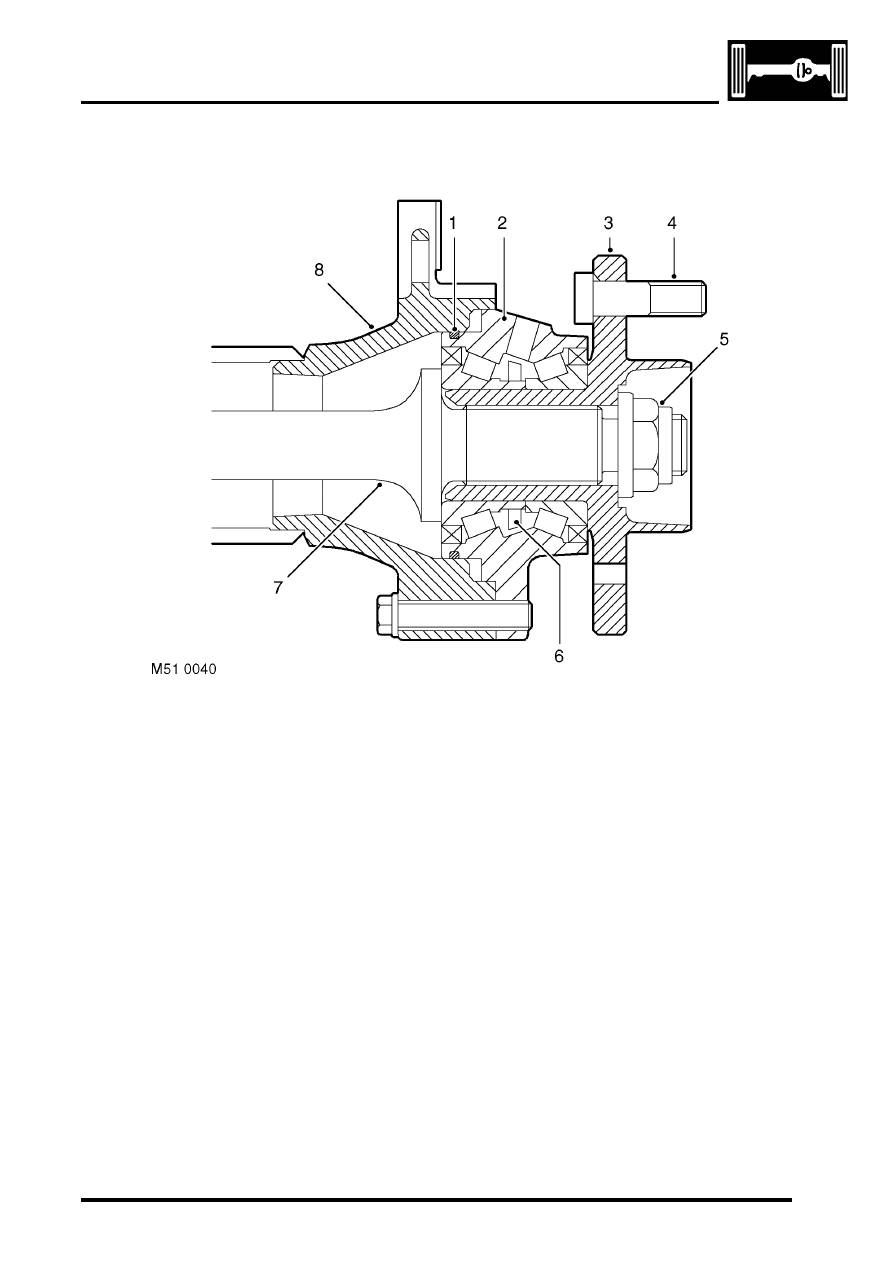
Wheel hub
Section through wheel hub
1 'O' ring
2 Hub bearing
3 Hub flange
4 Wheel stud
5 Stake nut
6 ABS sensor ring
7 Drive shaft
8 Axle casing
Each wheel hub consists of a hub flange pressed into a hub bearing.
The hub flange is splined to accept the outboard end of the drive shaft, which is secured to the hub flange with a stake
nut. Five studs are installed in the hub flange for the wheel nuts, and a threaded hole is provided for the brake disc
securing screw.
The outer race of the hub bearing is bolted to the end of the axle casing. An 'O' ring seals the joint between the outer
race and the axle casing to prevent leakage of differential lubricating oil. The hub bearing is a sealed unit which
contains twin opposed roller bearings, pre-packed with grease during manufacture. A toothed ABS sensor ring is
integrated into the inner race of the hub bearing. An opening in the outer race of the hub bearing accommodates the
ABS sensor.
Drive shaft
Each drive shaft consists of a solid rod, splined at both ends.