Discovery 2. Manual - part 145


  Index      Land Rover     Land Rover Discovery 2 - service manual 1999 year


Search            


Content   ..  143  144  145  146   ..


Discovery 2. Manual - part 145


AUTOMATIC GEARBOX - ZF4HP22 - 24

DESCRIPTION AND OPERATION

44-11

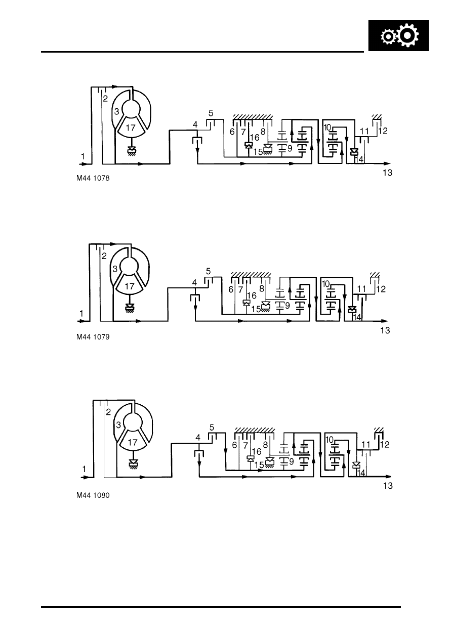
2nd Gear (D selected)

Clutches (4), (6), (7) and (11) are engaged. Freewheel (15) overruns. The hollow shaft with the sun wheel of gear set 

(9) is locked. Gear set (10) also rotates as a solid unit.

3rd Gear (D selected)

Clutches (4), (5), (7) and (11) are engaged. Freewheels (15) and (16) are overrun. Gear sets (9) and (10) rotate as a 

solid unit.

4th Gear (D selected)

Clutches (4), (5), (7) and (12) are engaged. Freewheels (14), (15) and (16) are overrun. Gear set (9) rotates as a solid 

unit. The hollow shaft with the sun wheel of gear set (10) is locked.

AUTOMATIC GEARBOX - ZF4HP22 - 24

44-12

DESCRIPTION AND OPERATION

Reverse gear

Clutches (5), (8) and (11) are engaged. The front planet gear carrier of gear set (9) is locked. Gear set (10) also rotates 

as a solid block.

Gear position switch
The gear position switch outputs signals that are related to the position of the selector lever assembly. The switch is 
installed on the selector shaft on the left side of the gearbox. Slotted mounting holes allow the switch to be turned 
relative to the shaft for adjustment. A fly lead connects the switch to the vehicle wiring.

Movement of the selector lever assembly turns the selector shaft, which operates six pairs of contacts in the switch. 
The pairs of contacts are identified as the W, X, Y, Z, Park/Neutral and Reverse contacts. When closed:

l

The W, X, Y and Z contacts output a 12V ignition supply from the BCU.

l

The Park/Neutral contacts output an earth.

l

The Reverse contacts output a 12V ignition supply from the passenger compartment fuse box.

The outputs of the W, X, Y and Z contacts are monitored by the EAT ECU and the BCU to determine the position of 
the selector lever assembly.

Gear position switch W, X, Y, Z outputs

The Park/Neutral contacts output to the BCU and, on diesel models, the ECM. The Reverse contacts output to the 
BCU, the reversing lamps, the SLABS ECU and, where fitted, the ACE ECU and the electrochromic interior mirror.

Switch 

contacts

Output

P

R

N

D

3

2

1

W

12V

-

12V

12V

-

-

-

X

-

12V

12V

-

12V

-

-

Y

-

-

12V

12V

12V

-

12V

Z

-

-

-

12V

12V

12V

-

AUTOMATIC GEARBOX - ZF4HP22 - 24

DESCRIPTION AND OPERATION

44-13

Oil cooler

Inlet connection
Fixing bracket
Outlet connection

Fixing bracket
Temperature sensor

Transmission fluid from the gearbox is circulated through a cooler attached to the front of the radiator. Quick release 
connectors on the transmission fluid lines attach to connections on each end tank of the cooler. A temperature sensor 
on the RH end tank provides the instrument pack with an input of transmission fluid temperature. If the temperature 
exceeds a preset limit, the instrument pack illuminates the transmission temperature warning lamp. The warning lamp 
remains illuminated until the temperature of the fluid returns within limits.

EAT ECU
The EAT ECU operates the solenoid valves in the gearbox to provide automatic control of gear shifts and torque 
converter lock-up. The EAT ECU is attached to a protective bracket which is secured to the cabin floor below the LH 
front seat. A 55 pin connector links the EAT ECU to the vehicle wiring.

Software in the EAT ECU monitors hard wired inputs and exchanges information with the ECM on a Controller Area 
Network (CAN) bus to determine gear shift and torque converter lock-up requirements. Resultant control signals are 
then output to the gearbox solenoid valves.

AUTOMATIC GEARBOX - ZF4HP22 - 24

44-14

DESCRIPTION AND OPERATION

EAT ECU connector

EAT ECU connector pin details

Pin No.

Description

Inputs/Outputs

1 to 4

Not used

-

5

Pressure regulator solenoid valve (MV 4)

Output

6

Power earth

-

7

Not used

-

8

Gear position switch, X contacts

Input

9

Gear position switch, Z contacts

Input

10 to 12

Not used

-

13

Transmission high/low switch

Input

14

Gearbox output shaft speed sensor, negative

Input

15

Gearbox output shaft speed sensor cable screen

-

16

CAN, high

Input/Output

17 to 24

Not used

-

25

Sport mode warning lamp

Output

26

Battery power supply

Input

27

Not used

-

28

Electronics earth

-

29

Not used

-

30

Shift control solenoid valve (MV 1)

Output

31

Diagnostics, K line

Input/Output

32

Converter lock-up solenoid valve (MV 3)

Output

33

Shift control solenoid valve (MV 2)

Output

34

Not used

-

35

Not used

-

36

Gear position switch, W contacts

Input

37

Gear position switch, Y contacts

Input

38 to 41

Not used

-

42

Gearbox output shaft speed sensor, positive

Input

43

Not used

-

44

CAN, low

Input/Output

45

Mode switch

Input

46 to 50

Not used

-

51

Manual mode warning lamp

Output

52

Not used

-

53

Solenoid valves power supply

Output

54

Ignition power supply

Input

55

Not used

-


Content   ..  143  144  145  146   ..