Discovery 2. Manual - part 47


  Index      Land Rover     Land Rover Discovery 2 - service manual 1999 year


Search            


Content   ..  45  46  47  48   ..


Discovery 2. Manual - part 47


ENGINE - V8

OVERHAUL 12-2-61

Gasket - cylinder head

$% 12.29.02.01 

Disassembly

1. Remove inlet manifold gasket.  


 + 

 ENGINE - V8, OVERHAUL, Gasket - 

inlet manifold.

2. RH cylinder head:  Remove auxiliary drive belt 

tensioner. 

3. RH cylinder head:  Remove bolts securing 

alternator mounting bracket and remove 
bracket. 

4. Noting their fitted order, disconnect ht leads 

from spark plugs. 

5. Progressively remove 4 bolts securing  the 

rocker shaft and remove rocker shaft. 

6. Remove push rods and store in their fitted 

order. 

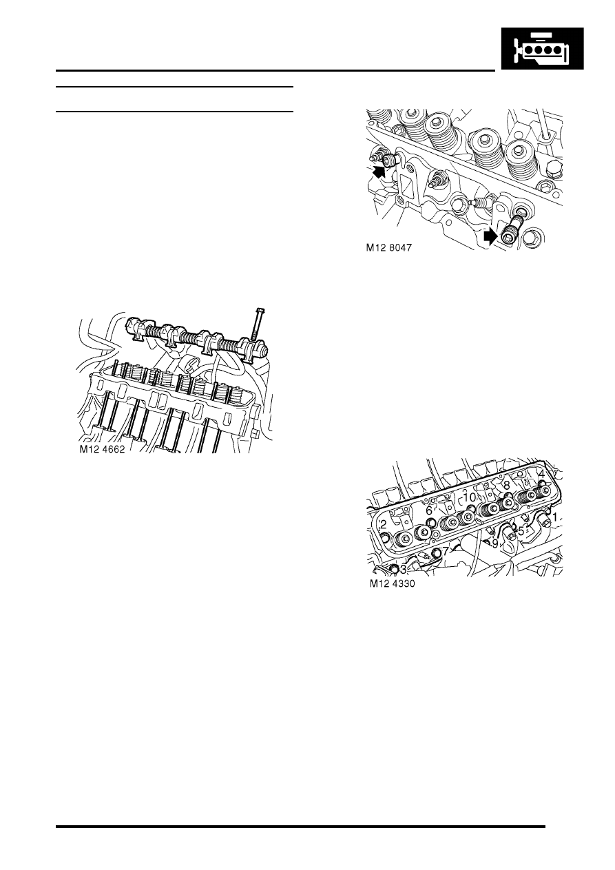
7. Models with SAI: Using a 9 mm hexagonal 

drive bit, remove 2 air injection adapters from 
cylinder head; discard adapters.

To release the adapter thread locking agent 
and prevent damage to the cylinder head, 
remove the adapters by alternately loosening 
then tightening slightly. Repeat this procedure 
until adapters are removed.

CAUTION: Do not use air tools to remove 
adapters.

8. Working in the sequence shown remove 10 

bolts  securing the cylinder head to block. 
Discard the bolts.

9. Remove cylinder head. 

ENGINE - V8

12-2-62 OVERHAUL

10. Remove cylinder head gasket. 

CAUTION: Support both ends of cylinder 
head on blocks of wood. 

Inspect

1. Clean mating faces of cylinder block and  head 

using suitable gasket removal spray and  a 
plastic scraper, ensure that bolt holes in  block 
are clean and dry. 

CAUTION: Do not use a metal scraper or 
machined surfaces may be damaged.

2. Check head and block faces for warping  and 

pitting. 

l

Maximum cylinder head warp = 0.05 mm 
(0.002 in).

Note: Cylinder head can be refaced to 0.50 

mm (0.02 in) maximum below head height – 
See cylinder head overhaul.

3. Models with SAI: Using a 5/8 in x 20 TPI ( 

threads per inch) UNF tap having a class 2A 
thread, remove deposits from secondary air 
injection adapter tappings in cylinder head.

CAUTION: Ensure that tap used has 20 TPI.

Reassembly

1. Ensure that cylinder head bolt holes are clean 

and dry.

2. Fit cylinder head gasket with the word   TOP 

uppermost. 

CAUTION: Gaskets must be fitted dry.

3. Carefully fit cylinder head and locate  on 

dowels. 

4. Lightly lubricate new cylinder head  bolt threads 

with clean engine oil. 

5. Noting that bolts 1, 3 and 5 are longer than the 

remainder, fit bolts and tighten in the  sequence 
shown to 20 Nm (15 lbf.ft) then  turn through 90 

°

,  then a further 90 

°

CAUTION: Do not 

tighten bolts 180

°

 in one operation. 

6. Models with SAI: Fit new air injection adapters 

and using a 9 mm hexagonal drive bit, tighten 
to 33 Nm (24 lbf.ft).

CAUTION: Do not use an air tool to tighten 
adapters.

7. Clean the push rods, Lubricate ends of push 

rods with clean  engine oil, and fit  in their 
removed order. 

8. Clean bases of rocker pillars and mating  faces 

on cylinder head. 

9. Clean contact surfaces on rockers, valves and 

push rods. 

10. Lubricate contact surfaces and rocker  shaft 

with clean engine oil. 

11. Fit rocker shaft assembly and engage  push 

rods. 

12. Fit rocker shaft bolts and progressively  tighten 

to 40 Nm (30 lbf.ft). 

13. Connect ht leads to spark plugs in their correct 

fitted order. 

14. RH cylinder head:  Position alternator 

mounting bracket, fit bolts and tighten to 40 Nm 
(30 lbf.ft).

15. RH cylinder head:  Fit auxiliary drive belt 

tensioner. 

16. Fit inlet manifold gasket.  


 + 

 ENGINE - V8, OVERHAUL, Gasket - 

inlet manifold.

ENGINE - V8

OVERHAUL 12-2-63

Cylinder head - overhaul 

$% 12.29.19.01 

Disassembly

1. Remove cylinder head gasket. 


 + 

 ENGINE - V8, OVERHAUL, Gasket - 

cylinder head.

2. Loosen screw on tool LRT-12-034

3. Fit tool LRT-12-034  to valve  and tighten screw 

to compress valve spring  sufficiently to release 
collets from valve  spring cap. 

4. Remove 2 collets and release valve spring  

compressor. 

5. Remove valve spring cap and valve   spring. 
6. Remove valve from cylinder head. 
7. Remove and discard valve stem oil seal. 
8. Repeat above operations for remaining  valves. 
9. Keep valves, springs, caps and collets  in their 

fitted order. 

Inspect

1. Clean mating faces of cylinder block and  head 

using suitable gasket removal spray and  a 
plastic scraper, ensure that bolt holes in  block 
are clean and dry. 

CAUTION: Do not use a metal scraper or 
machined surfaces may be damaged.

2. Clean cylinder head, valve springs,  valves and 

inlet valve guide bores. Ensure  all loose 
particles of carbon are removed on  completion. 

3. Models with SAI: Using a 5/8 in x 20 TPI ( 

threads per inch) UNF tap having a class 2A 
thread, remove deposits from secondary air 
injection adapter tappings in cylinder head.

CAUTION: Ensure that tap used has 20 TPI.

4. Check head and block faces for warping  and 

pitting. Maximum warp = 0.05 mm (0.002 in).

5. Check cylinder head height at each end of 

head. Renew a head which is outside limits.

22.94 mm (0.903 in) - New

62.56 mm (2.463 in) - New

ENGINE - V8

12-2-64 OVERHAUL

6. Cylinder head can be refaced to 0.50 mm (0.02 

in) max. below head height.

7. Remove carbon deposits from exhaust  valve 

guide using a 8.70 mm (0.34 in) diameter 
reamer  inserted from combustion face side of  
cylinder head. 

NOTE: Modified inlet valves, exhaust valves 
and valve guides were fitted to 4.0 litre engines 
from the following engine numbers: 55D 
05678A; 56D 50788A and 97D 05505A and are 
fitted to all 4.6 litre engines. 

8. Modified inlet valves may be identified by 

measuring the distance 'A' from the valve head 
face to the top of the undercut on the valve 
stem:

l

Early valves = 29.5 to 30.5 mm (1.16 to 1.20 
in)

l

Later valves = 32.5 to 33.5 mm (1.28 to 1.32 
in)

9. Modified exhaust valves may be identified as 

follows:

l

Early valves 'A' – Chrome finish

l

Later valves 'B' – Black nitrided finish

10. Modified valve guides are 5 mm (0.211 in) 

shorter than the early type, the overall length is 
now 57 mm (2.24 in); the reduction in length 
being the distance the guide protrudes into the 
combustion chamber side of the cylinder head.

NOTE: The modified valves and guides may be 
fitted to 4.0 litre engines prior to the above 
numbers in cylinder sets. Early type valves will 
continue to be supplied for early 4.0 litre 
engines but if valve guides are found to be 
worn, the later valves and guides must be fitted.


Content   ..  45  46  47  48   ..