Discovery 2. Manual - part 35


  Index      Land Rover     Land Rover Discovery 2 - service manual 1999 year


Search            


Content   ..  33  34  35  36   ..


Discovery 2. Manual - part 35


ENGINE - V8

REPAIRS 12-2-13

REPAIRS

Seal - crankshaft - rear 

$% 12.21.20 

Remove

1. Automatic gearbox models:Remove 

converter drive plate.
 

 + 

 ENGINE - V8, REPAIRS, Plate - drive 

- automatic.

2. Manual gearbox models:Remove flywheel.


 + 

 ENGINE - V8, REPAIRS, Flywheel.

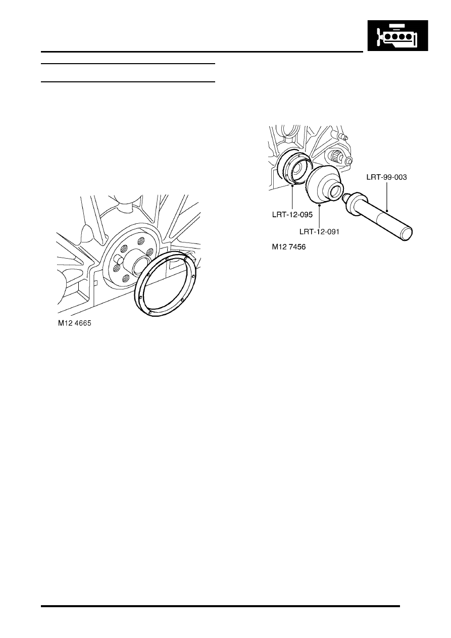
3. Carefully remove oil seal from cylinder block to 

avoid damage to seal location or running 
surface on crankshaft. Discard seal.

Refit

1. Ensure both seal location and running  surface 

on crankshaft are clean. 

2. Lubricate replacement oil seal with engine oil.

3. Lubricate seal guide LRT-12-095 with engine 

oil, fit seal guide to crankshaft. 

4. Fit oil seal squarely onto crankshaft and  

remove seal guide  LRT-12-095.

5. Fit seal into location using tools LRT-12-091 

and LRT-99-003.

6. Automatic gearbox models:Fit converter 

drive plate.
 

 + 

 ENGINE - V8, REPAIRS, Plate - drive 

- automatic.

7. Manual gearbox models:Fit flywheel.


 + 

 ENGINE - V8, REPAIRS, Flywheel. 

ENGINE - V8

12-2-14 REPAIRS

Gasket - cylinder head - LH 

$% 12.29.02 

Remove

1. Remove inlet manifold gasket. 


 + 

 MANIFOLDS AND EXHAUST 

SYSTEMS - V8, REPAIRS, Gasket - inlet 
manifold - lower.

2. Noting their fitted order, disconnect ht leads 

from spark plugs. 

3. Remove bolt securing engine harness to  rear 

of cylinder head. 

4. LH drive models: Remove brake servo heat 

shield.
 

 + 

 MANIFOLDS AND EXHAUST 

SYSTEMS - V8, REPAIRS, Heat shield - 
brake servo - Without Secondary Air 
Injection.

5. Remove 8 bolts securing exhaust manifold to 

cylinder head, release manifold and collect 2 
gaskets.

6. Progressively remove 4 bolts securing  the 

rocker shaft and remove rocker shaft. 

7. Remove push rods. Store push rods in their 

fitted order.

8. Models with SAI: Using a 9 mm hexagonal 

drive bit, remove 2 air injection adapters from 
cylinder head; discard adapters.

Note: To release the adapter thread locking 
agent and prevent damage to the cylinder 
head, remove the adapters by alternately 
loosening then tightening slightly. Repeat this 
procedure until adapters are removed.

CAUTION: Do not use air tools to remove 
adapters.

ENGINE - V8

REPAIRS 12-2-15

9. In the sequence shown, remove 10 bolts  

securing the cylinder head to block. Discard the 
bolts.

10. Remove cylinder head. 

CAUTION: Support both ends of cylinder 
head on blocks of wood. 

11. Remove cylinder head gasket. 

Refit

1. Clean mating faces of cylinder block and  head 

using suitable gasket removal spray and  a 
plastic scraper, ensure that bolt holes in  block 
are clean and dry. Clean mating faces of 
cylinder head and exhaust manifold.

CAUTION: Do not use a metal scraper or 
machined surfaces may be damaged.

2. Check head and block faces for warping and 

pitting. If out of specification, renew head.

3. Models with SAI: Using a 5/8 in x 20 TPI 

(threads per inch) UNF tap having a class 2A 
thread, remove deposits from secondary air 
injection adapter tappings in cylinder head.

CAUTION: Ensure that tap used has 20 TPI.

4. Fit cylinder head gasket with the word   'TOP' 

uppermost. 

CAUTION: Gaskets must be fitted dry.

5. Carefully fit cylinder head and locate  on 

dowels. 

6. Lightly lubricate new cylinder head  bolt threads 

with clean engine oil. 

7. Noting that bolts 1, 3 and 5 are longer than the 

remainder, fit cylinder head bolts and tighten in 
the  sequence shown to 20 Nm (15 lbf.ft) then  
90

°

 , and finally a further 90

°

 . 

CAUTION: Do not tighten bolts 180

°

 in one 

operation.

8. Models with SAI: Fit new air injection adapters 

and using a 9 mm hexagonal drive bit, tighten 
to 33 Nm (24 lbf.ft).

CAUTION: Do not use an air tool to tighten 
adapters.

9. Clean push rods. 

10. Lubricate ends of push rods with clean  engine 

oil. 

11. Fit push rods in their removed order. 
12. Clean bases of rocker pillars and mating  faces 

on cylinder head. 

13. Clean contact surfaces on rockers, valves  and 

push rods. 

14. Lubricate contact surfaces and rocker  shaft 

with clean engine oil. 

15. Fit rocker shaft assembly and engage  push 

rods. 

16. Fit rocker shaft bolts and progressively  tighten 

to 40 Nm (30 lbf.ft). 

ENGINE - V8

12-2-16 REPAIRS

17. Using new gaskets, position exhaust manifold 

to cylinder head, fit bolts and using sequence 
shown, tighten initially to 15 Nm (11 lbf.ft), then 
finally to 36 Nm (28 lbf.ft). 

18. LH drive models: Fit brake servo heat shield.


 + 

 MANIFOLDS AND EXHAUST 

SYSTEMS - V8, REPAIRS, Heat shield - 
brake servo - Without Secondary Air 
Injection.

19. Fit  engine harness bolt and tighten to 22 Nm 

(16 lbf.ft). 

20. Connect ht leads to spark plugs in their correct 

fitted order. 

21. Fit inlet manifold gasket. 


 + 

 MANIFOLDS AND EXHAUST 

SYSTEMS - V8, REPAIRS, Gasket - inlet 
manifold - lower.

Gasket - cylinder head - RH

$% 12.29.03 

Remove

1. Remove inlet manifold gasket. 


 + 

 MANIFOLDS AND EXHAUST 

SYSTEMS - V8, REPAIRS, Gasket - inlet 
manifold - lower.

2. Remove bolt securing auxiliary drive belt 

tensioner and remove tensioner. 

3. Remove 4 bolts securing alternator  mounting 

bracket and remove bracket. 

4. Noting their fitted order, disconnect ht leads 

from spark plugs. 

5. Remove bolt securing engine earth lead. 


Content   ..  33  34  35  36   ..