Discovery electrical Manual - part 29
INSTRUMENTS
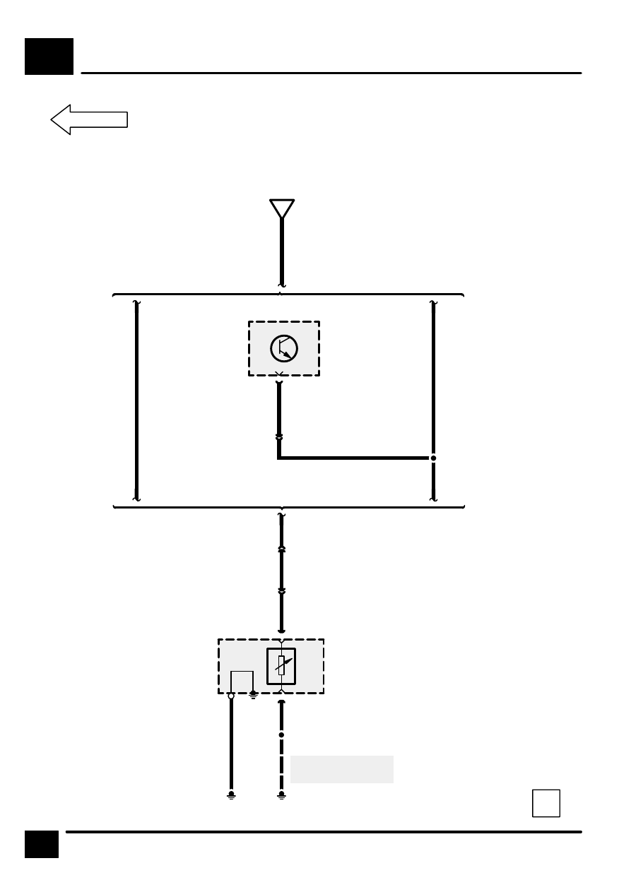
E1
6
1
C434
Z134
Fuel Pump Mod-
ule
[1]
Fuel Level
Sensor
[1]
B
2
C434
B
See Ground Dis-
tribution
S415
E400
E404
E1-5
C
GB
Z132
Engine Control
Module (ECM)
S2100
Except NAS
NAS
Except NAS
NAS
7
C1017
GB
13
C1026
23
C277
2
C407