Discovery (1995+): Body Repair Manual - part 41
77
PANEL REPAIRS
6
PROCEDURES
12. Apply adhesive sealant to panel joint surfaces.
See GENERAL SPECIFICATION DATA,
Information
Offer Up and Align
Offer up new panel and align with associated panels.
Clamp into position using welding clamps or Mole
grips. Where a joggle or brace joint is being adopted,
make a set in the original panel joint edge or insert a
brace behind the joint.
NOTE: In cases where access for welding
clamps is difficult, it may be necessary to
use tack welds.
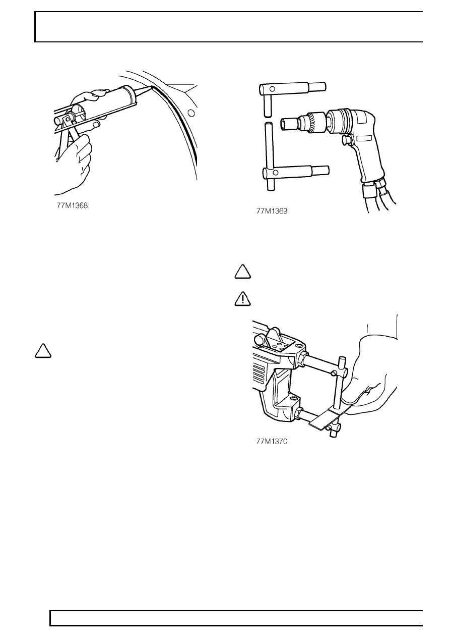
Welding
13. Select arms for resistance spot welding and
shape electrode tips using a tip trimmer.
NOTE: To maintain efficiency, the tips will
require regular cleaning with emery cloth.
CAUTION: Use electrode arms not
exceeding 300mm (12 in) in length.
14. Fit resistance spot welding arms and test
equipment for satisfactory operation, using test
coupons. Where monitoring equipment is not
available, verify weld strength by checking that
metal around the weld puddle pulls apart under
tension during pulling.