Discovery (1995+): Body Repair Manual - part 27


  Index      Land Rover     Discovery Body Repair Manual - 1995 year


Search            


Content   ..  25  26  27  28   ..


Discovery (1995+): Body Repair Manual - part 27


76

CHASSIS AND BODY

46

REPAIR

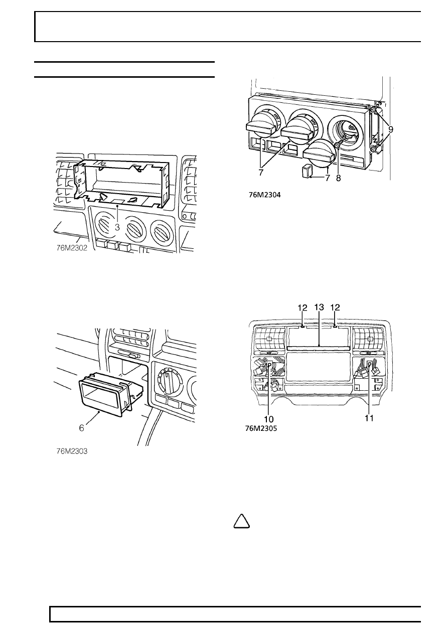
DASH PANEL CENTRAL LOUVRE PANEL

Service repair no - 76.46.42

Remove

1. Disconnect battery negative lead.
2. Remove radio.

See ELECTRICAL, Repair.

3. Release tags securing radio cage to louvre

panel and remove cage.

4. Remove clock.

See ELECTRICAL, Repair.

5. Release 4 coin tray securing tags.

6. Remove coin tray.

7. Remove 3 heater control and blower switch

knob.

8. Remove 2 screws securing heater graphic

display panel and remove panel.

9. Remove 4 screws securing heater control unit to

panel.

10. Working through coin tray aperture, remove

screw securing panel.

11. Working through clock aperture, remove screw

securing panel.

12. Loosen 2 uppermost panel retaining screws.

NOTE: On some models the panel is fitted
with an LED. In this case, manoeuvre LED
from panel and disconnect.

13. Remove panel retaining screw cover.

CHASSIS AND BODY

47

REPAIR

14. Remove 2 screws securing louvre panel.
15. Remove louvre panel from dash panel.

Refit

16. Position louvre panel, feed harness connectors

through their correct apertures,and align to dash
panel.

CAUTION: When refitting avoid trapping of
electrical wiring.

17. Fit and tighten screws securing louvre panel.
18. Fit panel retaining screw cover.
19. Position heater control unit to panel and secure

with screws.

20. Fit heater graphic display panel and secure with

screws.

21. Fit heater control and blower switch knobs.
22. Fit clock.

See ELECTRICAL, Repair.

23. Position coin tray and secure to tags.
24. Position radio cage, feed electrical connectors

and aerial through cage, and position to panel.

25. Bend back radio cage retaining tags.
26. Fit radio.

See ELECTRICAL, Repair.

27. Connect battery negative lead.

DASH PANEL ASSEMBLY

Service repair no - 76.46.23

Remove

1. Move front seats to rearmost position.
2. Disconnect battery negative lead.
3. Disconnect air bag multiplugs under dash panel.

CAUTION: When air bags are fitted,
reference must be made to the Airbag
Supplementary Restraint System section.

4. Remove passenger glove box.
5. Remove driver’s side access panel.
6. Remove centre console assembly.

See this

section.

7. Remove airbag from steering wheel.

See

SUPPLEMENTARY RESTRAINT SYSTEM,
Repair.

8. Remove passenger’s airbag from dash panel.

See SUPPLEMENTARY RESTRAINT SYSTEM,
Repair.

9. Release clamp and lower steering column.

10. Remove steering wheel.

See STEERING,

Repair.

11. Remove column switch.

See

SUPPLEMENTARY RESTRAINT SYSTEM,
Repair.

12. Remove instrument binnacle.

See

ELECTRICAL, Repair.

13. Remove radio.

See ELECTRICAL, Repair.

14. Remove exterior mirrors switch panel.
15. Remove coin tray.
16. Remove switch panel.
17. Remove clock.
18. Undo screw securing mounting bracket and

position passenger’s side relay assembly aside.

19. Set heater controls fully clockwise.

76

CHASSIS AND BODY

48

REPAIR

20. Note position of levers, disconnect heater control

cables from levers and outer cable from retaining
clips.

21. Remove 4 bolts securing dash panel to centre

lower mounting brackets.

22. Remove 4 bolts securing dash panel to side

lower mounting brackets.

23. Undo 4 screws and remove 2 driver’s knee

bolster pads from below steering column.

24. Remove 4 nuts securing instrument mounting

bracket to dash panel.

25. With assistance: Manoeuvre dash panel

partially rearward.

26. Driver’s side: Disconnect 6 multiplugs

connecting dash harness to main harness.

27. Disconnect 3 multiplugs connecting dash

harness to fusebox.

28. With assistance: Lift dash panel rearward to

clear fixings and remove from vehicle.

CHASSIS AND BODY

49

REPAIR

Refit

CAUTION: When refitting avoid trapping
electrical wiring.

29. Reverse removal procedure.
30. With assistance: Position dash panel and

connect dash harness multiplugs to fusebox and
main harness.

31. Reverse removal procedure. Ensure dash panel

upper bracket studs are located before the 4
lower brackets.

32. Reverse removal procedure. Disconnect

glovebox switch Lucars to ease fitting of relay
bracket.

WINDSCREEN GLASS

Service repair no - 76.81.01

Information

The following equipment is required:

Cutting wire and handles

Windscreen repair kit (see Technical
Bulletin).

See Electrical Trouble Shooting

Manual.Windscreen Glass Replacement.

Sealant applicator gun.

Suction cup lifters.

The following materials are included in the windscreen
repair kit:

Glass cleaning solvent - ’Betawipe’ Glass
activator (yellow cap).

Cotton buds.

Glass primer - ’Betaprime’(green cap).

Body primer - ’Betaprime’ paint/plastic
primer (red cap).

Betaseal Adhesive sealant.

NOTE: The adhesive sealant cures in 6 to 8
hours

CAUTION: Once existing sealant is cut, the
exposed surfaces oxidises in
approximately 90 minutes. The refit

procedure must be completed within this time
span to prevent the sealant oxidising, to effect a
satisfactory joint.

CAUTION: If the windscreen aperture body
flange shows signs of corrosion it must be
treated with anti corrosion primer and

repainted. Newly painted areas must then be left
for 8 hours or more before applying adhesive
sealant.


Content   ..  25  26  27  28   ..