Discovery (1995+): Body Repair Manual - part 17


  Index      Land Rover     Discovery Body Repair Manual - 1995 year


Search            


Content   ..  15  16  17  18   ..


Discovery (1995+): Body Repair Manual - part 17


76

CHASSIS AND BODY

6

REPAIR

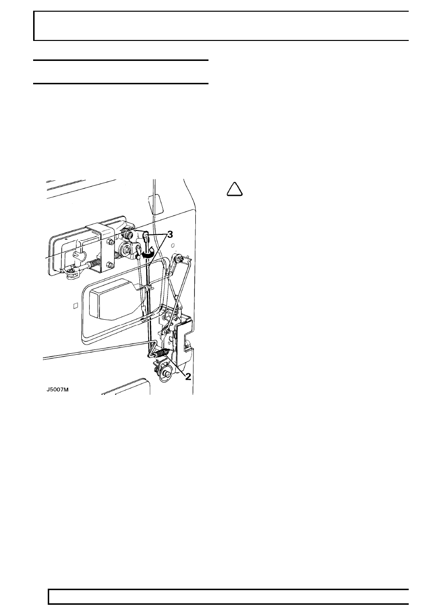
ADJUSTMENT-FRONT DOOR LOCK AND HANDLE
ASSEMBLY

Service repair no - 76.37.47

Inside door release handle to lock

1. Refit the inside door release handle surround

before any adjustment is made, allowing the
handle to be set from the correct operating
position.

2. At the lock end of the interior handle connecting

rod, rotate the spring tensioned nyloc nut
clockwise or counter-clockwise, as necessary to
shorten or extend the operating length of the rod.

Outside door release handle to lock

3. Disconnect the connecting rod from the plastic

ferrule at the rear of the outer door release
handle. Rotate the rod clockwise or
counter-clockwise to shorten or extend the
operating length as necessary.

NOTE: Door release should be effective
before the total handle movement is
exhausted to provide a small overthrow

movement.

CHASSIS AND BODY

7

REPAIR

REAR SIDE DOORS

Service repair no - 76.28.02

Remove

1. Disconnect battery negative lead.
2. Detach the convoluted grommet from the ’B’

post.

3. Withdraw the door harness multiplugs from the

’B’ post and disconnect them.

4. Remove the bolts and washers securing the

check strap to the ’B’ post.

WARNING: Instruction 5 MUST BE carried
out with assistance.

5. Remove the door hinge ’C’ clips from the hinge

posts and with assistance carefully lift the door
from the vehicle.

Refit

6. Reverse removal procedure. Fitting new ’C’ clips

if the existing ones are worn or distorted.

7. Check the operation of the door and lock. If

necessary, adjust the door and striker.

Adjust

8. Adjust the door by adding or removing shims

between the hinge and the door to move the
door forward or rearward in the opening.

9. To adjust the door up, down or in and out of the

opening, loosen the screws securing the hinges
to the door, adjust as necessary and retighten
the screws to the correct torque value.

10. Adjustment of the door striker is identical to the

procedure for front doors.

NOTE: If it is necessary to remove the
hinges from the ’B’ post they must be
refitted in exactly the same position, using

an equal thickness of shims to those removed.

76

CHASSIS AND BODY

8

REPAIR

REAR SIDE DOOR - TRIM PANEL

Service repair no - 76.34.04

Remove

1. Disconnect battery negative lead.
2. Remove the two securing screws and detach the

door pull from its mounting brackets.

3. Remove the securing screw and detach the

interior door release handle surround.

4. Where applicable remove the window winder or

release electric switch and disconnect.

5. Detach the trim panel by inserting a trim panel

removing tool between the trim panel and the
inner door panel, gently prise out the plastic
securing clips from their respective holes in the
inner panel.

6. Lift the trim panel over the remote button and

clear of the door. Where applicable disconnect
the electrical plug from the window lift switch and
withdraw the panel.

NOTE: With the trim panel removed the
remote button and rod will fall from its
location in the bellcrank. Observe its

correct location and withdraw from the door
panel.

7. If a new trim panel is to be fitted, remove the

window lift switch, door bin and remote button
finisher from the existing trim panel and fit them
to the new panel.

Refit

8. Reverse removal procedure. Ensuring correct

fitment of the sill button operating rod.

CHASSIS AND BODY

9

REPAIR

REAR SIDE DOOR LOCK, INSIDE AND OUTSIDE
RELEASE HANDLES

Service repair no - 76.37.13/32

Remove

1. Ensure that the window is in the fully closed

position.

2. Disconnect battery negative lead.
3. Remove the interior trim panel from the door.

See this section.

4. Remove the plastic vapour barrier sheet.
5. Disconnect the inside release handle control rod

by pulling it from its location in the door lock.

6. Disconnect the sill locking control rod from the

lock by releasing the metal clip.

7. Disconnect the outside release handle control

rod by pulling it out of the plastic ferrule.

8. Remove the two countersunk screws from the

door edge and the single screw and shakeproof
washer from the inner door panel. Retrieve any
spacing washers which may be fitted between
the inner door panel and lock.

9. Withdraw the lock through the upper rear

opening in the inner door panel.

NOTE: If necessary the following items
can be removed.

10. Remove the two nuts, shakeproof washers and

retaining bracket securing the outer release
handle which are accessible through the upper
rear cut-out on the inner door panel.

11. Carefully detach the handle from the outer door

panel.

12. Remove the two screws and plain washers

securing the inside release handle to the inner
door panel and withdraw the handle complete
with connecting rod.

13. Disconnect the sill button connecting rod from

the bellcrank and withdraw the rod complete with
sill button.

Sill locking bellcrank

14. Using a small screwdriver, or length of 3.175 mm

(1/8 in) diameter rod, press the plastic locking
pins through the respective square inserts in the
inner door panel.

15. Release the bellcranks from the inner door panel

and unhook the respective connecting rods.

16. Withdraw the bellcranks from inside the door

panels.

NOTE: When refitting the bellcranks the
locking pins are entered into the square
insert from outside and pressed in flush.


Content   ..  15  16  17  18   ..