Discovery (1995+): Body Repair Manual - part 13


  Index      Land Rover     Discovery Body Repair Manual - 1995 year


Search            


Content   ..  11  12  13  14   ..


Discovery (1995+): Body Repair Manual - part 13


75

SUPPLEMENTARY RESTRAINT SYSTEM

12

REPAIR

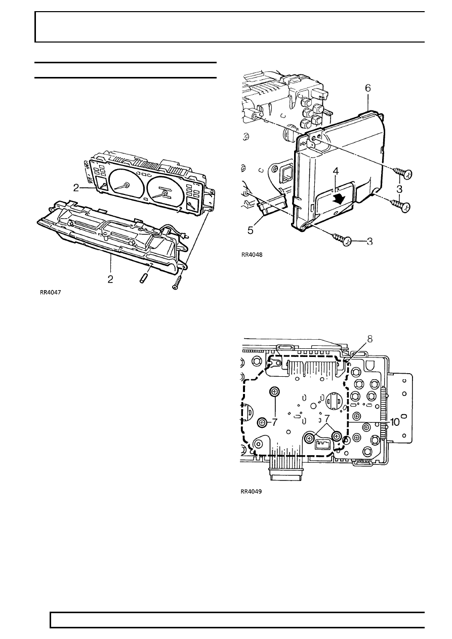
SRS WARNING LIGHT BULBS

Service repair no - 76.73.74

Remove

1. Remove instrument binnacle.

See

ELECTRICAL, Repair.

2. Remove window and face plate from instrument

panel.

3. Remove 3 screws securing ECU to instrument

panel.

4. Release and remove small cover from ECU.
5. Disconnect multiplug from ECU.
6. Remove ECU

7. Remove 4 screws securing tachometer.
8. Remove tachometer.

SUPPLEMENTARY RESTRAINT SYSTEM

13

REPAIR

9. Carefully remove 2 screws securing face plate to

tachometer.

10. Release warning light housing from tachometer

circuit board.

11. Carefully (to avoid damage to tachometer needle

and spindle), tilt and remove warning light
housing.

12. Remove 2 warning light bulbs.

Refit

13. Reverse removal procedure.
14. Fit new warning light bulbs.
15. Carefully fit warning light housing, ensuring that

locating pegs engage correctly and that retaining
clips lock housing into position.

16. Ensure that tachometer needle is on the correct

side of its stop.

17. Fit instrument binnacle.

See ELECTRICAL,

Repair.

75

SUPPLEMENTARY RESTRAINT SYSTEM

14

REPAIR

AIRBAG HARNESS

Service repair no - 86.70.63

Remove

1. Remove driver’s airbag.

See this section.

2. Remove passenger’s airbag.

See this section.

3. Remove dash panel assembly.

See CHASSIS

AND BODY, Repair.

4. Remove heater blower unit.

See HEATING

AND VENTILATION, Repair.

5. Remove heater and cooler unit.

See AIR

CONDITIONING, Repair.

Pre 97 MY

6. Remove 3 screws securing expansion tank and

position expansion tank aside.

7. Disconnect multiplug from each crash sensor.
8. Release airbag harness from clips and ties along

the bulkhead and each valance.

9. Displace airbag harness grommet to inside of

bulkhead and feed harness through bulkhead.

All Models

10. Disconnect multiplug from airbag control unit.
11. Release airbag harness from under carpet.

12. Release ties securing harness along toeboard.
13. Disconnect steering wheel airbag multiplug.
14. Release airbag harness from driver’s side and

remove.

Refit

15. Reverse removal procedure.

CAUTION: Ensure harness is correctly
routed in harness protector and that all
securing clips and ties are correctly

engaged and harness is undamaged. Ensure all
connections are fully engaged and retained by
their latches.

SUPPLEMENTARY RESTRAINT SYSTEM

15

REPAIR

AIRBAG MANUAL DEPLOYMENT

CAUTION: Deployment in the vehicle will
damage the steering wheel; if the vehicle
is not being scrapped deploy the module

away from the vehicle in accordance with the
separate procedure.

If a vehicle is to be scrapped and contains an
undeployed airbag module, the module must be
manually deployed. This operation should only be
carried out using the following recommended manual
deployment procedure.

Before deployment is started the deployment tool self
test procedure should be carried out.

Deployment tool SMD 4082/1 self test procedure

1. Insert BLUE and YELLOW connectors of tool

lead into corresponding sockets on face of tool.

2. Connect crocodile clips of second tool lead to

battery, RED to positive and BLACK to negative.

3. RED "READY" light should illuminate.
4. Press and hold both operating buttons.

5. GREEN "DEFECTIVE" light should illuminate.
6. Release both operating buttons.
7. RED "READY" light should illuminate.
8. Disconnect tool from battery.
9. Disconnect blue and yellow connectors from tool

face sockets.

10. Self test now complete.

Deployment with module fitted to vehicle

These guidelines are written to aid authorised
personnel to carry out the safe disposal of the airbag
module when fitted to the vehicle.

WARNING: Only use the LAND ROVER
approved deployment equipment. Deploy
airbag module in a well ventilated

designated area. Ensure airbag module is not
damaged or ruptured before deploying.

1. Carry out deployment tool self test.

2. Release 2 turnbuckles securing lower panel to

dash, remove lower panel.


Content   ..  11  12  13  14   ..