Land Rover Discovery. Manual - part 243


  Index      Land Rover     Land Rover Discovery - service 1995-1996 year


Search            


Content   ..  241  242  243 


Land Rover Discovery. Manual - part 243


ENGINE

76

OVERHAUL

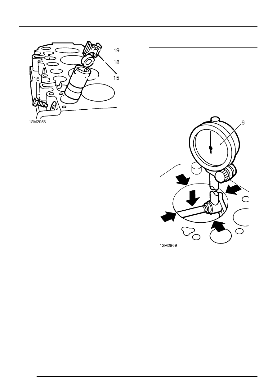
15. Insert each cam follower guide into its original

location in the cylinder block.

16. Fit new retaining bolt, locate end of bolt in cam

follower guide.

17. Tighten bolt to 14 Nm.
18. Fit roller ensuring that reference mark made

during removal is towards front of cylinder
block.

19. Fit cam follower slide ensuring that word

’FRONT’ or mark ’F’ is towards front of cylinder
block.

20. Repeat above procedures for remaining cam

follower assemblies.

21. Fit a dry, new gasket to baffle plate.
22. Fit baffle plate, fit 3 bolts and finger tighten in

their original locations.

23. Bolts are tightened when fuel injection pump is

fitted.

Cylinder block - inspection

1. Thoroughly clean cylinder block, ensure all bolt

holes are clean and dry.

2. Remove all traces of carbon from cylinder head

gasket face.

3. Remove all traces of gaskets using suitable

gasket removal spray and a plastic scraper.

4. Check all studs for damage, replace as

necessary.

5. Check core plugs for corrosion and signs of

leakage, replace as necessary.

6. Using an internal micrometer, take 2

measurements at 90

°

to each other at top of

bore. The difference between the 2
measurements is the ovality of the bore.
Maximum ovality = 0.127 mm

7. Repeat measurements 50 mm from bottom of

each cylinder bore.

8. Measure from side to side from below wear

ridge at top of bore and above wear ridge at
bottom of bore. The difference between the 2
measurements is the taper.
Maximum taper = 0.254 mm

ENGINE

OVERHAUL

77

9. Check cylinder bore overall wear, measure at

several points from side to side, the largest
diameter recorded is the maximum wear.
Cylinder bore - standard = 90.47 mm
1st rebore oversize = 90.73 mm
2nd rebore oversize = 90.98 mm
Maximum wear = 0.177 mm

CAUTION: Do not de-glaze cylinder bores.

10. Cylinder bores which are worn in excess of

0.177 mm over the above bore sizes must be
rebored and the appropriate oversize pistons
and rings fitted.

CAUTION: Cylinder bores must be honed
to finished size.

11. Fit oil pick-up and drain pipes and sump.
12. Fit cylinder head.
13. Fit flywheel/drive plate housing.
14. Fit timing belt rear cover and oil pump.
15. Fit timing belt.
16. Fit fuel injection pump.
17. Fit oil filter head.
18. Fit fuel lift pump.
19. Fit brake servo vacuum pump.

ENGINE

DATA, TORQUE & TOOLS

1

ENGINE DATA

Rocker shaft
Rocker shaft wear - maximum

0.025 mm

. . . . . . . . . . . . . . . . . .

Rocker arm shaft to bush clearance - maximum

0.12 mm

. . . .

Valve clearance - inlet and exhaust

0.20 mm

. . . . . . . . . . . . . .

Oil pump
Outer rotor to housing clearance

0.025 to 0.075 mm

. . . . . . . . . . . . . . . .

Inner to outer rotor clearance

0.025 to 0.075 mm

. . . . . . . . . . . . . . . . . .

Outer rotor end-float

0.026 to 0.135 mm

. . . . . . . . . . . . . . . . . . . . . . . . .

Relief valve spring free length

68.0 mm

. . . . . . . . . . . . . . . . . .

Cylinder head
Cylinder head maximum warpage

0.08 mm

. . . . . . . . . . . . . . .

Maximum movement of valve to guide

0.15 mm

. . . . . . . . . . .

Valve stem diameter:
Inlet

7.96 mm

. . . . . . . . . . . . . . . . . . . . . . . . . . . . . . . . . . . . . .

Exhaust

7.94 mm

. . . . . . . . . . . . . . . . . . . . . . . . . . . . . . . . . . .

Valve head stand down:
Inlet

0.81 to 1.09 mm

. . . . . . . . . . . . . . . . . . . . . . . . . . . . . . . . . . . . . .

Exhaust

0.86 to 1.14 mm

. . . . . . . . . . . . . . . . . . . . . . . . . . . . . . . . . . .

Valve seat insert face angle:
Inlet

60

°

. . . . . . . . . . . . . . . . . . . . . . . . . . . . . . . . . . . . . .

Exhaust

45

°

. . . . . . . . . . . . . . . . . . . . . . . . . . . . . . . . . . .

Valve face angle:
Inlet

60

°

00’ to 60

°

30’

. . . . . . . . . . . . . . . . . . . . . . . . . . . . . . . . . . . . . .

Exhaust

45

°

00’ to 45

°

30’

. . . . . . . . . . . . . . . . . . . . . . . . . . . . . . . . . . .

Valve spring free length

46.28 mm

. . . . . . . . . . . . . . . . . . . . . . .

Timing belt tension on torque wrench
Used belt

12 Nm

. . . . . . . . . . . . . . . . . . . . . . . . . . . . . . . . . .

New belt

15 Nm

. . . . . . . . . . . . . . . . . . . . . . . . . . . . . . . . . . .

Drive plate - automatic gearbox
Setting height

12.4 mm

. . . . . . . . . . . . . . . . . . . . . . . . . . . . . . .

ENGINE

2

DATA, TORQUE & TOOLS

Crankshaft
Maximum bearing journal ovality

0.040 mm

. . . . . . . . . . . . . . . .

Maximum bearing journal run-out

0.076 mm

. . . . . . . . . . . . . . .

Main bearing journal diameter

63.475 to 63.487 mm

. . . . . . . . . . . . . . . . . .

Service limit

63.36 mm

. . . . . . . . . . . . . . . . . . . . . . . . . . . . . . . .

Regrind diameter

63.225 to 63.237 mm

. . . . . . . . . . . . . . . . . . . . . . . . . . . .

Big-end journal diameter

58.725 to 58.744 mm

. . . . . . . . . . . . . . . . . . . . . .

Service limit

58.637 mm

. . . . . . . . . . . . . . . . . . . . . . . . . . . . . . . .

Regrind diameter

58.475 to 58.494 mm

. . . . . . . . . . . . . . . . . . . . . . . . . . . .

Main and big-end bearing oversizes available

0.25 mm

. . . . . .

Main bearing clearance

0.031 to 0.079 mm

. . . . . . . . . . . . . . . . . . . . . . .

Crankshaft end-float

0.05 to 0.15 mm

. . . . . . . . . . . . . . . . . . . . . . . . .

Thrust washer oversizes available:
1st oversize

0.063

. . . . . . . . . . . . . . . . . . . . . . . . . . . . . . . .

2nd oversize

0.127 mm

. . . . . . . . . . . . . . . . . . . . . . . . . . . . . . .

Big-end bearing clearance

0.025 to 0.075 mm

. . . . . . . . . . . . . . . . . . . . .

Connecting rod end-float

0.15 to 0.35 mm

. . . . . . . . . . . . . . . . . . . . . .

Camshaft
End-float

0.1 to 0.2 mm

. . . . . . . . . . . . . . . . . . . . . . . . . . . . . . . . . .

Pistons and connecting rods
Piston diameter:
Standard

90.395 mm

. . . . . . . . . . . . . . . . . . . . . . . . . . . . . . . . . .

1st oversize

90.649 mm

. . . . . . . . . . . . . . . . . . . . . . . . . . . . . . . .

2nd oversize

90.903 mm

. . . . . . . . . . . . . . . . . . . . . . . . . . . . . . .

Piston to cylinder bore clearance

0.075 mm

. . . . . . . . . . . . . . . .

Connecting rod misalignment - maximum

0.075 mm per 25.4 mm

. . . . . . . . .

Piston rings
Fitted gap in cylinder bore:
Top compression

0.40 to 0.65 mm

. . . . . . . . . . . . . . . . . . . . . . . . . . . .

2nd compression

0.30 to 0.50 mm

. . . . . . . . . . . . . . . . . . . . . . . . . . . .

Oil control rails

0.30 to 0.60 mm

. . . . . . . . . . . . . . . . . . . . . . . . . . . . . .

Ring to groove clearance:
Top compression

0.167 to 0.232 mm

. . . . . . . . . . . . . . . . . . . . . . . . . . . .

2nd compression

0.05 to 0.08 mm

. . . . . . . . . . . . . . . . . . . . . . . . . . . .

Oil control ring assembly

0.05 to 0.08 mm

. . . . . . . . . . . . . . . . . . . . . .

Cylinder block
Cylinder bore maximum ovality

0.127 mm

. . . . . . . . . . . . . . . . .

Cylinder bore maximum taper

0.254 mm

. . . . . . . . . . . . . . . . . .

Cylinder bore maximum wear

0.177 mm

. . . . . . . . . . . . . . . . . .

Cylinder bore size:
Standard

90.47 mm

. . . . . . . . . . . . . . . . . . . . . . . . . . . . . . . . . .

For 1st oversize piston

90.73 mm

. . . . . . . . . . . . . . . . . . . . . . .

For 2nd oversize piston

90.98 mm

. . . . . . . . . . . . . . . . . . . . . . .


Content   ..  241  242  243