Land Rover Discovery. Manual - part 238


  Index      Land Rover     Land Rover Discovery - service 1995-1996 year


Search            


Content   ..  236  237  238  239   ..


Land Rover Discovery. Manual - part 238


ENGINE

56

OVERHAUL

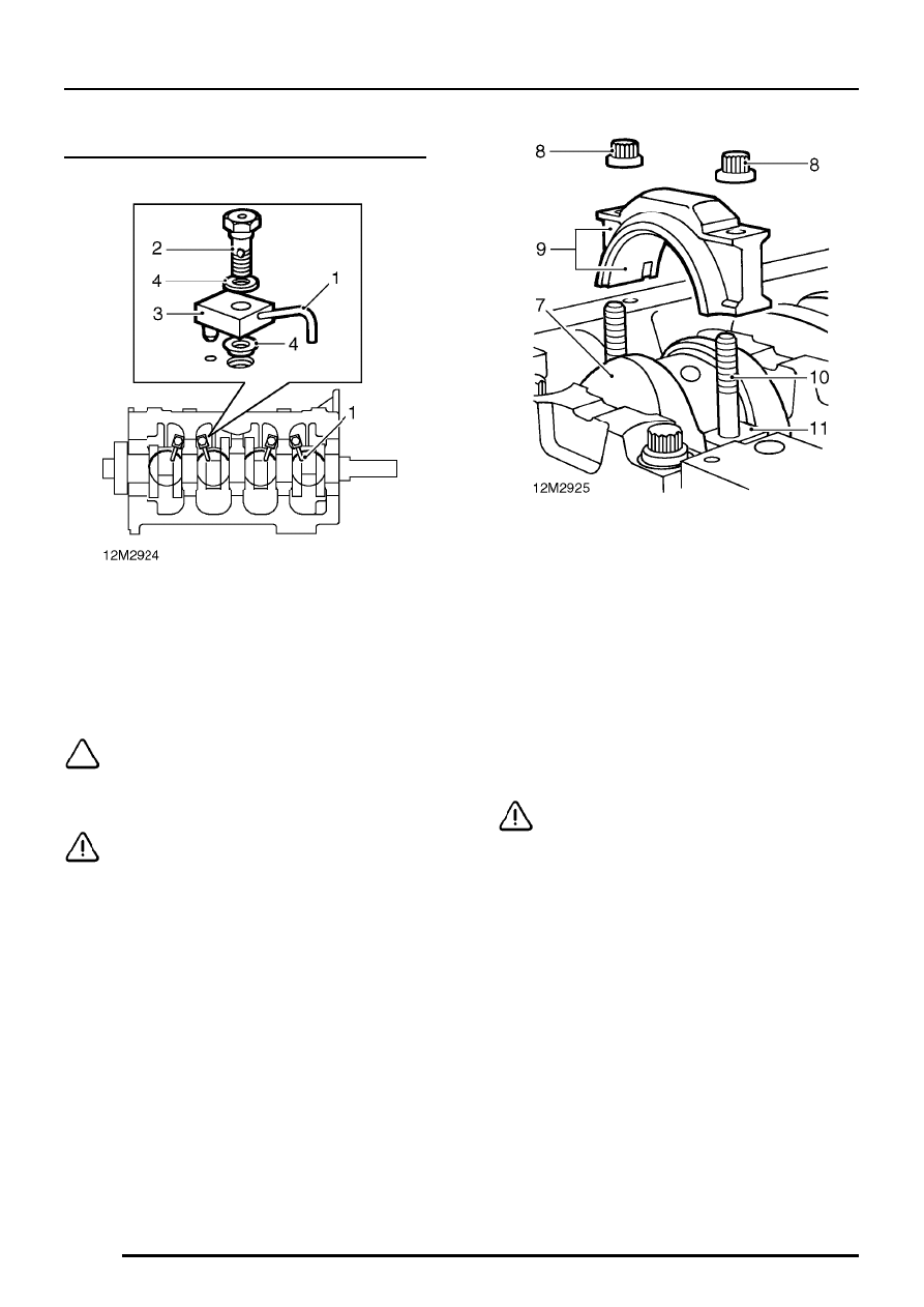
Big-end bearings - remove

1. Suitably identify each oil jet tube to its fitted

location.

2. Remove bolt securing each oil jet tube

assembly to cylinder block.

3. Remove oil jet tube assemblies.

NOTE: Dowel located.

4. Recover sealing washers.

CAUTION: Oil jet tube bolts incorporate a
non-return valve.

5. Temporarily fit crankshaft pulley bolt.
6. Suitably identify fitted position of each big-end

bearing cap to its connecting rod and each
connecting rod to its respective cylinder bore.

7. Rotate crankshaft to bring numbers 1 and 4

connecting rods to BDC.

8. Remove and discard 2 nuts securing each

big-end bearing cap.

9. Remove numbers 1 and 4 big-end bearing

caps, recover bearing shells.

10. Slide suitable pieces of plastic tubing over

each connecting rod bolt.

11. Push numbers 1 and 4 connecting rods up

cylinder bores until they are clear of crankshaft
journals.

12. Repeat above procedures to remove numbers

2 and 3 big-end bearings.

CAUTION: Big-end bearing shells must
always be replaced.

ENGINE

OVERHAUL

57

Crankshaft and main bearings - remove

1. Suitably identify each main bearing cap and its

fitted direction in crankcase.

2. Starting at number 3 main bearing cap and

working outwards, progressively slacken, then
remove bearing cap bolts. Keep bolts with their
respective main bearing caps.

3. Using the fingers only, rock each main bearing

cap until it is released from its retaining dowels.

CAUTION: Do not tap main bearing caps
sideways to release.

4. Remove and discard oil seals from number 5

main bearing cap.

5. Recover lower main bearing shells from

bearing caps.

6. Using assistance, remove crankshaft.

7. Recover grooved thrust washers and upper

main bearing shells.

CAUTION: Main bearing shells and thrust
washers must always be replaced.

8. Remove pistons and connecting rods.

ENGINE

58

OVERHAUL

Crankshaft - inspection

NOTE: Crankshafts may be reground 0.25
mm undersize on both main and big-end
journals.

See Crankshaft - regrinding.

1. Clean crankshaft and main bearing caps,

ensure oilways are clear.

2. Check main and big-end journals for signs of

scoring, excessive wear and overheating.

3. Check main and big-end bearing journals for

wear and ovality, make 3 checks at 120

°

intervals in centre of journals.

Maximum ovality = 0.040 mm
Main bearing journal diameter = 63.475 to
63.487 mm
Service limit = 63.36 mm
Regrind diameter = 63.225 to 63.237 mm

Big-end bearing journal diameter = 58.725 to
58.744 mm
Service limit = 58.637 mm
Regrind diameter = 58.475 to 58.494 mm

4. If bearing journal diameters are less than

service limit, crankshaft may be reground to
specified regrind diameter and 0.25 mm
oversize bearing shells fitted.

5. Using a micrometer, measure diameter at each

end of main and big-end bearing journals.

6. From measurements obtained, calculate taper

of each journal.
Maximum journal taper - end to end = 0.025
mm

7. Support each end of crankshaft in Vee blocks.
8. Position a DTI with stylus contacting centre

main bearing journal.

9. Rotate crankshaft and check run-out does not

exceed 0.076 mm.

CAUTION: If run-out exceeds above figure,
renew crankshaft.

ENGINE

OVERHAUL

59

Crankshaft - regrinding

NOTE: Crankshaft journals may be
reground to the following dimensions.

Main bearing journals = 63.225 to 63.237 mm
Big-end bearing journals = 58.475 to 58.494 mm

CAUTION: Rotation of crankshaft must be
in an ANTI-CLOCKWISE direction when
viewed from flywheel end of crankshaft.

1. Grind journals ensuring that grinding wheel

travels beyond edge of journal to avoid
formation of a step B.

CAUTION: Take care not to damage fillet
radius C.

2. Final finishing should be carried out using a

static lapping stone with crankshaft rotating in
a CLOCKWISE direction when viewed from
flywheel end of crankshaft.

3. On completion of grinding operations,

thoroughly clean crankshaft ensuring that all oil
passages are clear.

Main bearing caps and saddles - inspection

1. Ensure main bearing cap bolts and bolt holes

are clean and dry.

2. Fit each main bearing cap less bearing shells

to its correct location ensuring that direction
marks on cap are facing the correct way.

3. Fit and tighten each pair of main bearing cap

bolts to 133 Nm.

4. Slacken the bolt on one side of each main

bearing cap.

5. Using feeler gauges, check that there is no gap

between each main bearing cap and saddle on
the side of the cap with the slackened bolt.

6. If a gap exists, replace main bearing cap and

re-check.

7. If gap still exists, cylinder block must be

replaced.

CAUTION: Do not attempt to machine
main bearing caps or saddles.

8. Remove main bearing caps.

CAUTION: Keep main bearing cap bolts
with their respective caps.


Content   ..  236  237  238  239   ..