Land Rover Discovery. Manual - part 228


  Index      Land Rover     Land Rover Discovery - service 1995-1996 year


Search            


Content   ..  226  227  228  229   ..


Land Rover Discovery. Manual - part 228


ENGINE

16

OVERHAUL

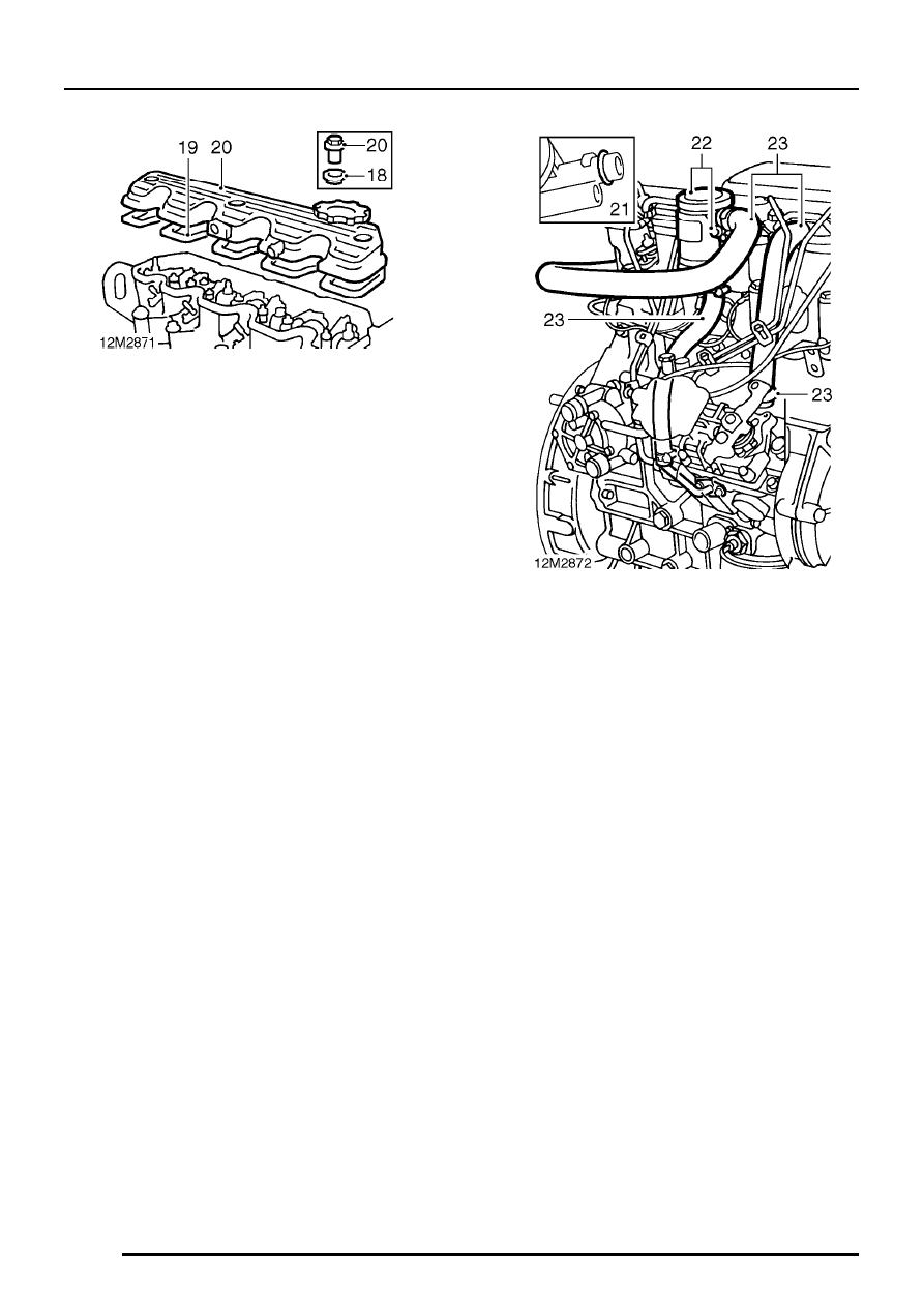
18. Check sealing washers for damage or

distortion, replace as necessary.

19. Position a new gasket - dry to rocker cover.
20. Position rocker cover to cylinder head, fit 3

flange nuts and working from centre outwards,
tighten to 10 Nm.

21. Lubricate a new ’O’ ring with engine oil and fit

to crankcase breather cyclone unit.

22. Fit cyclone unit to rocker cover, fit bolt and

tighten to 9 Nm.

23. Connect breather hoses to cyclone unit, rocker

cover and cylinder block.

ENGINE

OVERHAUL

17

VALVE CLEARANCES - ADJUST

CAUTION: To prevent possibility of
damage to cam follower seatings, it is
essential that ball ends of tappet adjusting

screws are seated in recess in push rods and
that ball end of each push rod is correctly
located in cam follower slide.

1. Rotate crankshaft by means of crankshaft

pulley bolt in a clockwise direction until number
8 valve ( counting from front of engine ) is fully
open.

2. Using feeler gauges and a screwdriver, adjust

clearance of number 1 valve.
Valve clearance - all valves = 0.20 mm

3. Tighten tappet adjusting screw locknut when

clearance is correct.

4. Adjust the remaining valve clearances in the

following sequence:
Adjust number 3 clearance with number 6
valve fully open
Adjust number 5 clearance with number 4
valve fully open
Adjust number 2 clearance with number 7
valve fully open
Adjust number 8 clearance with number 1
valve fully open
Adjust number 6 clearance with number 3
valve fully open
Adjust number 4 clearance with number 5
valve fully open
Adjust number 7 clearance with number 2
valve fully open

5. Upon completion, re-check all clearances and

adjust as necessary.

ENGINE

18

OVERHAUL

CYLINDER HEAD

Remove

1. Remove rocker shaft.
2. Remove fuel injectors.
3. Remove glow plugs.

4. Using sequence shown, progressively slacken

then remove and discard 18 bolts securing
cylinder head.

5. Using assistance, remove cylinder head.

NOTE: Dowel located.

6. Remove cylinder head gasket.

CAUTION: Identify cylinder head gasket
thickness by the number of holes in the
edge of the gasket between numbers 3

and 4 injector ports. Replacement gasket must
be of the same thickness as the original unless a
replacement cylinder head, crankshaft and/or
pistons are fitted.

- See Cylinder head gasket

selection.

7. Discard cylinder head gasket.

8. Remove 2 bolts securing coolant outlet elbow.
9. Remove coolant outlet elbow.

10. Remove thermostat from housing.

11. Remove 4 bolts securing thermostat housing to

cylinder head, remove housing.

12. Remove and discard gasket.
13. Remove all traces of gasket using suitable

gasket removal spray and a plastic scraper.

ENGINE

OVERHAUL

19

14. Remove 2 bolts securing engine front lifting

bracket, remove bracket.

Valves and springs - remove

1. Support cylinder head clear of valves, use a

hollow drift and tap each valve spring cap to
free collets.

2. Position cylinder head on its side.

3. Using tool LRT-12-034 compress valve spring.
4. Remove 2 collets from valve stem.
5. Remove tool LRT-12-034.


Content   ..  226  227  228  229   ..