Land Rover Discovery. Manual - part 179


  Index      Land Rover     Land Rover Discovery - service 1995-1996 year


Search            


Content   ..  177  178  179  180   ..


Land Rover Discovery. Manual - part 179


76

CHASSIS AND BODY

48

REPAIR

20. Note position of levers, disconnect heater control

cables from levers and outer cable from retaining
clips.

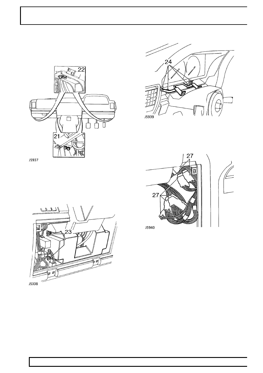
21. Remove 4 bolts securing dash panel to centre

lower mounting brackets.

22. Remove 4 bolts securing dash panel to side

lower mounting brackets.

23. Undo 4 screws and remove 2 driver’s knee

bolster pads from below steering column.

24. Remove 4 nuts securing instrument mounting

bracket to dash panel.

25. With assistance: Manoeuvre dash panel

partially rearward.

26. Driver’s side: Disconnect 6 multiplugs

connecting dash harness to main harness.

27. Disconnect 3 multiplugs connecting dash

harness to fusebox.

28. With assistance: Lift dash panel rearward to

clear fixings and remove from vehicle.

CHASSIS AND BODY

49

REPAIR

Refit

CAUTION: When refitting avoid trapping
electrical wiring.

29. Reverse removal procedure.
30. With assistance: Position dash panel and

connect dash harness multiplugs to fusebox and
main harness.

31. Reverse removal procedure. Ensure dash panel

upper bracket studs are located before the 4
lower brackets.

32. Reverse removal procedure. Disconnect

glovebox switch Lucars to ease fitting of relay
bracket.

WINDSCREEN GLASS

Service repair no - 76.81.01

Information

The following equipment is required:

Cutting wire and handles

Windscreen repair kit (see Technical
Bulletin).

See Electrical Trouble Shooting

Manual.Windscreen Glass Replacement.

Sealant applicator gun.

Suction cup lifters.

The following materials are included in the windscreen
repair kit:

Glass cleaning solvent - ’Betawipe’ Glass
activator (yellow cap).

Cotton buds.

Glass primer - ’Betaprime’(green cap).

Body primer - ’Betaprime’ paint/plastic
primer (red cap).

Betaseal Adhesive sealant.

NOTE: The adhesive sealant cures in 6 to 8
hours

CAUTION: Once existing sealant is cut, the
exposed surfaces oxidises in
approximately 90 minutes. The refit

procedure must be completed within this time
span to prevent the sealant oxidising, to effect a
satisfactory joint.

CAUTION: If the windscreen aperture body
flange shows signs of corrosion it must be
treated with anti corrosion primer and

repainted. Newly painted areas must then be left
for 8 hours or more before applying adhesive
sealant.

76

CHASSIS AND BODY

50

REPAIR

NOTE: If heated front screen: 2 electrical
multiplug connectors are located under
the decker [cowl] panel. To access release

decker panel.

Remove

1. Remove windscreen wiper arms.

See WIPERS

AND WASHERS, Repair, wiper arms -
windscreen.

2. Remove rear view mirror and stickers from

glass.

3. Remove ’A’ post finishers.
4. Fit protective cover over dash panel and apply

masking tape to protect ’A’ posts.

5. Ease one end of bottom finisher away from

glass, pull to disengage finisher flange and
remove.

6. Lift lip of LH ’A’ post finisher and release sealing

strip along its length, pull to disengage finisher
flange from glass and remove.

7. Remove RH ’A’ post finisher.
8. Remove header finisher.
9. Apply masking tape to protect paint finish around

glass.

10. Prepare cutting wire in handle ’A’. Bend end of

wire to handle and tape over end.

11. Force cutting wire through sealer from inside and

100mm (3 7/8 in) from a top corner. Use a
needle if necessary to make a pilot hole.

12. Attach handle ’B’. Allow 200mm (7 7/8 in) of wire

between handles, tape over end of wire.

13. With an assistant on the inside: Wedge the

tube of the handle ’A’ between glass and body
flange 100mm (3 7/8 in) ahead of hole in sealer.

14. From the outside: Carefully cut sealer from

flange using a straight pull away from the glass.
Continue in 100mm (3 7/8 in) steps around the
glass, use a sawing action at the corners.

CAUTION: Along the bottom edge, great
care must be taken to cut up to the 2
supports, positions indicated on the

obscuration band (See item 18).

15. Remove handle ’B’, withdraw the cutting wire

and insert it through the sealer between the
supports. Refit handle ’B’.

CHASSIS AND BODY

51

REPAIR

16. Cut through sealer between the supports.

If heated front screen: Cut through the 2 wires
each side of the supports. Tape cut wires and
panels to prevent damage to bodywork when
screen is removed.

17. Attach suction cups to glass and lift glass from

body flange, cut sealer free around supports as
necessary.

WARNING: If glass has splintered: Protect
eyes and operate demister blower at
maximum speed to remove any glass from

ducts. Use a vacuum cleaner to remove glass
particles from inside the vehicle.

Refit

18. Check condition of supports, renew if necessary.

Locating studs must be at right angle to flange.

NOTE: The supports were fitted to early
vehicles and now replaced with nylon
sheaths.

19. Carefully cut back old sealant around body

flange to obtain a smooth surface 2mm (1/10in)
thick. DO NOT cut down to flange.

20. If refitting original glass: It must be free from

chips or cracks. Cut back old sealant around
glass to obtain a smooth surface 2mm (1/10 in)
thick. DO NOT cut down to glass surface.

CAUTION: Lay glass on felt covered
supports, do not stand on edge. Any
chipping of glass edge may develop into

cracks.

21. Align header finisher on top edge of glass, push

flange fully onto glass and use a wooden block
and mallet to ensure fit.

22. Carefully align each side finisher on edge of

glass, push flange fully onto glass and use a
wooden block and mallet to ensure fit.

23. Using a cotton bud, apply glass cleaning solvent

(yellow cap) to inside face of glass, 20mm (13/16
in) strip around inside of finishers and 30mm (1
1/8 in) wide along bottom edge. Immediately
wipe off solvent with a clean cloth.

CAUTION: Do not touch cleaned or primed
surfaces with fingers.


Content   ..  177  178  179  180   ..