Land Rover Discovery. Manual - part 120


  Index      Land Rover     Land Rover Discovery - service 1995-1996 year


Search            


Content   ..  118  119  120  121   ..


Land Rover Discovery. Manual - part 120


REAR AXLE AND FINAL DRIVE

1

OVERHAUL

AXLE DIFFERENTIAL ASSEMBLY

Service repair no - 51.15.07.

DISMANTLE

NOTE: Mark differential components so
their original positions relative to other
components is maintained. Bearing caps

must not be interchanged.

1. Remove axle shafts then differential assembly

fom axle.

2. Remove roll pin securing bearing nut locking

fingers to bearing caps. Remove locking fingers.

3. Loosen bearing cap bolts and mark caps for

assembly.

4. Using service tool LRT-54-508, remove bearing

adjusting nuts.

5. Remove bearing cap bolts and bearing caps.
6. Remove crown wheel differential unit and

bearings.

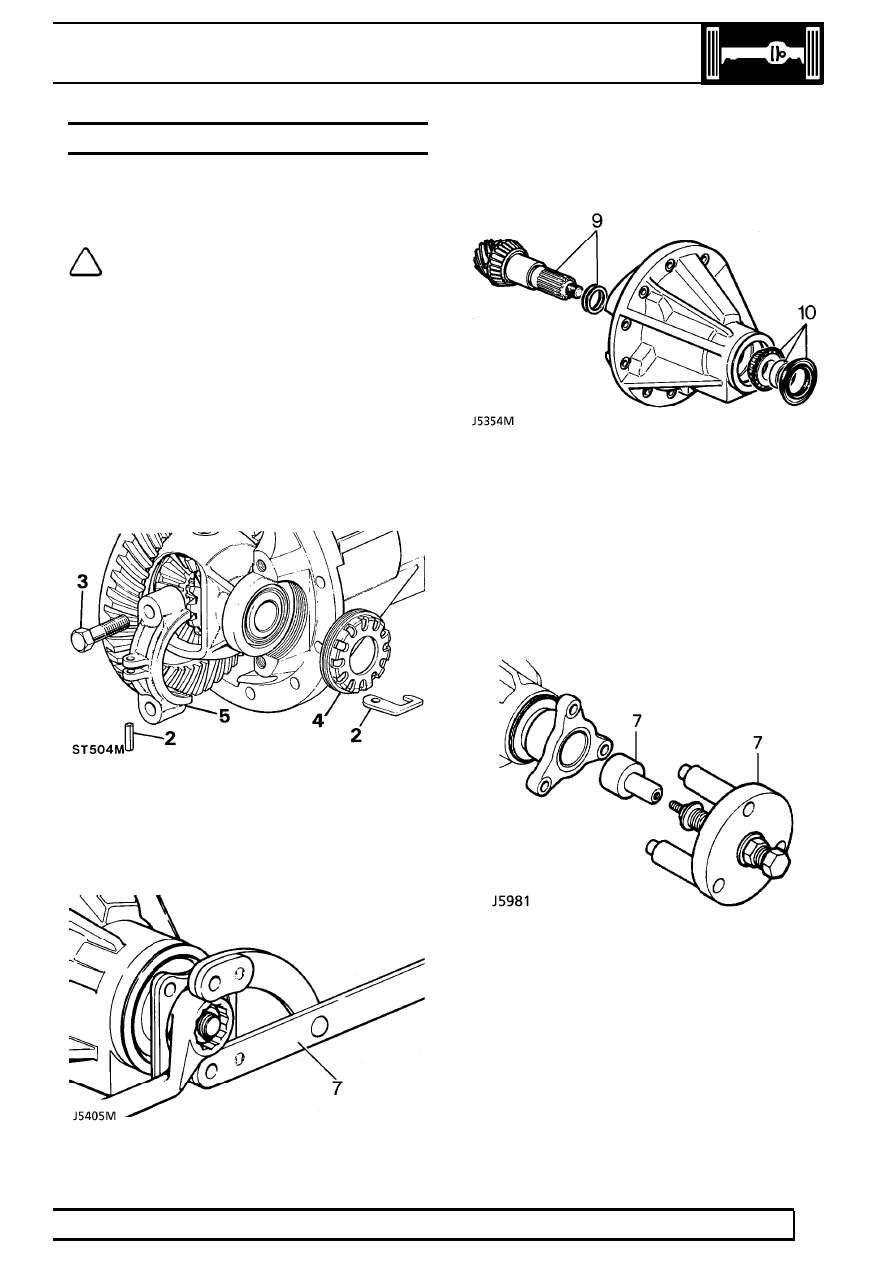
Remove pinion FRONT AXLE DIFFERENTIAL
ONLY

7. Remove pinion flange nut using service tool

LRT-51-003 to restrain flange.

8. Remove washer and pinion drive flange.

9. Remove pinion complete with bearing and outer

bearing shims.

10. Remove pinion flange oil seal, spacer and

bearing.

Remove pinion REAR AXLE DIFFERENTIAL ONLY

7. Remove pinion flange centralizing peg using

service tool LRT-51-008.

8. Remove pinion flange nut using service tool

LRT-51-003 to restrain flange.

9. Remove pinion complete with bearing and outer

bearing shims.

10. Remove pinion flange oil seal and bearing.

11. Using service tool LRT-54-505, remove pinion

head bearing track and shim and drive out outer
bearing of differential housing.

51

REAR AXLE AND FINAL DRIVE

2

OVERHAUL

12. Remove pinion head bearing with service tool

LRT-99-002.

13. Remove bolts and washers securing crown

wheel to differential flange. Remove crown
wheel.

14. Remove differential carrier bearings.
15. Remove circlips and extract differential cross

shaft.

16. Withdraw differential gears and pinions.
17. Clean all components.

INSPECTION

18. Check all bearings for wear and pitting.
19. Check all gears for wear, scuffing, pitting and

damaged teeth.

20. Supplied as matched sets are: crown wheel and

pinion, pinion housing and bearing caps.

ASSEMBLE

Differential gears

21. Fit differential gears to differential housing.
22. Fit differential cross shaft and circlips.

REAR AXLE AND FINAL DRIVE

3

OVERHAUL

23. Check gear for freedom of rotation and backlash.

Nominal backlash should be present. Excess
backlash necessitates replacement of gears or
differential housing.

24. Check serial number marked on pinion end face

matches that on crown wheel.

25. Clean and fit crown wheel.
26. Fit carrier bearings and assemble tracks to

bearings.

27. Place differential housing with crown wheel and

bearings in pinion housing.

28. Fit bearing caps and bolts. Do not tighten bolts.
29. Fit bearing adjusting nuts and adjust to obtain

zero end float.

30. Tighten bearing cap bolts to

90 Nm.

31. Check crown wheel for run-out. This should not

exceed 0,10 mm. If exceeded examine crown
wheel and mounting flange for burrs, grit, etc.
Refit and recheck. A buckled or damaged
differential housing flange is corrected by
replacing differential gear housing.

32. After checking run out remove differential

housing from pinion housing.

33. Remove crown wheel bolts and refit using

Loctite ’Studlock’. Tighten to

58 Nm.

34. Fit pinion head bearing track and original shim to

pinion housing. Use service tools LRT-54-505
and LRT-54-506. If fitting a new shim use
minimum 1.27 mm thickness.

51

REAR AXLE AND FINAL DRIVE

4

OVERHAUL

35. Fit pinion outer bearing track to pinion housing.

Use service tools LRT-54-505 and LRT-54-507.

36. Fit pinion head bearing to pinion. Use service

tool LRT-54-502.

37. Fit pinion into its location without shims for

bearing pre-load.

38. Fit outer bearing, and spacer (front axle

differential only).

39. Fit driving flange, washer and nut.

40. Do not fit oil seal at this stage.
41. Tighten pinion flange nut until force required to

rotate pinion is

3 Nm if new bearings are fitted.

This will pre-load bearings to check pinion height
dimension.

NOTE: If using original bearings, pre-load
figure is 1.5 Nm.

Drive pinion markings

NOTE: Markings on end face adjacent to
serial number are of no relevance to
servicing.

42. Figures marked on end face opposite to serial

number show in thousandths of an inch,
deviation from nominal, required to set pinion.
Pinions marked plus (+) must be set below
nominal. Pinions marked minus (-) must be set
above nominal. Unmarked pinions must be set at
nominal.


Content   ..  118  119  120  121   ..