Land Rover Discovery. Manual - part 94


  Index      Land Rover     Land Rover Discovery - service 1995-1996 year


Search            


Content   ..  92  93  94  95   ..


Land Rover Discovery. Manual - part 94


Mpi

5

REPAIR

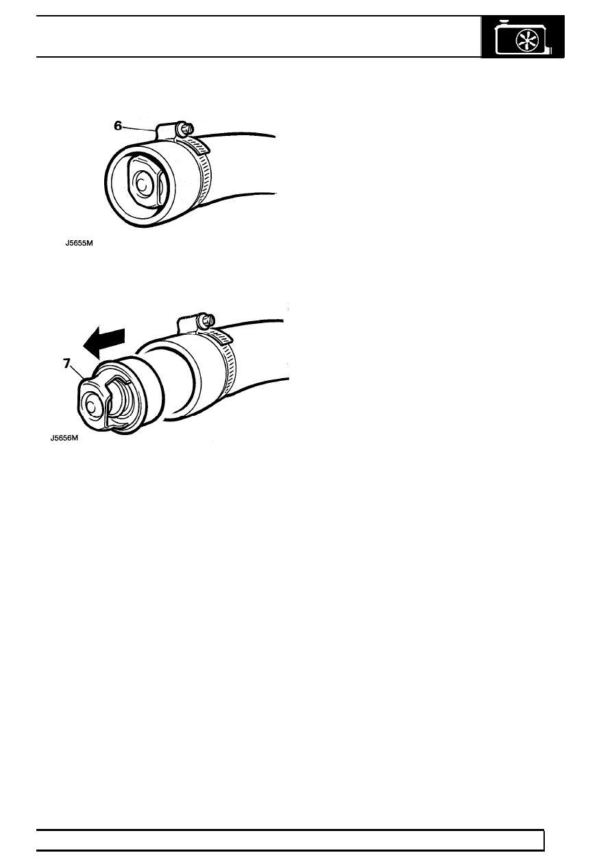
6. Remove clip securing thermostat in hose.

7. Lubricate hose in front of thermostat and

manoeuvre thermostat from hose.

Refit

8. Lubricate inside of top hose with liquid soap.
9. Manoeuvre thermostat into hose to previous

position.

10. Fit and tighten clip securing thermostat to top

hose.

11. Refit radiator hose.
12. Top-up cooling system.

MANIFOLD AND EXHAUST SYSTEM

1

DESCRIPTION AND OPERATION

CATALYTIC CONVERTERS - V8i

Description

Catalytic converters which form part of the engine
emission control system, are designed to ’clean’ the
exhaust gases, by closely controlling the fuel air ratio
delivered to the engine and converting the residual
exhaust compounds into products more acceptable to
the environment.

The front section of the exhaust system to each
cylinder bank contain the ceramic elements of the
catalytic converters. The oxygen sensors which
transmit information to the fuel ECU for control of the
mixture, are located in the exhaust down pipes.

The Hydrocarbons (HC), Nitogen oxides (NO

x

) and

Carbon monoxide (CO) emitted by the engine react
with the catalytic element and exhaust temperature to
convert the toxic gas, into Nitrogen (N), Carbon
dioxide (CO

2

) and water vapour.

Should the engine be supplied with a rich mixture
causing high CO in the exhaust gas, the ceramic
element will become coated and the useful life of the
catalyst reduced. If the mixture is too weak, excess
oxygen in the exhaust gas will cause the catalysts to
burn out.

1. Catalysts
2. Lambda oxygen sensors

MANIFOLD AND EXHAUST SYSTEM

1

REPAIR

EXHAUST SYSTEM COMPLETE

Service repair no - 30.11.01

To improve sealing and accuracy of assembly, a two
piece exhaust system is fitted.

NOTE: Ensure no exhaust leaks are
evident in either a new or old exhaust
system, as this will affect vehicle

performance.

WARNING: To prevent personal injury
occurring from a hot exhaust system, DO
NOT attempt to disconnect any

components until exhaust system has cooled
down.

30

MANIFOLD AND EXHAUST SYSTEM

2

REPAIR

Remove

Catalysts - remove and refit 1 to 5

1. Raise vehicle on a ramp [hoist].
2. Catalyst vehicles only: Disconnect two heated

oxygen sensor wiring connectors.

NOTE: NAS models have four heated
oxygen sensors fitted.

3. Remove two nuts securing rear exhaust

assembly to front exhaust assembly.

4. Remove nuts and release front downpipes from

manifolds. Discard gaskets.

5. Lower front exhaust assembly with catalysts (if

fitted), retain olive.

NOTE: Assistance is required for removing
and refitting rear exhaust assembly.

6. Remove bolts securing three hanger brackets to

chassis. Lower exhaust assembly onto rear axle.
Detach rubbers from hanging brackets.

7. Place extended axle stands underneath chassis,

in front of chassis mounted rear towing brackets.

8. Lower ramp[hoist] until vehicle weight is

supported securely on stands.

9. Lower ramp [hoist] until rear shock absorbers

are ALMOST fully extended.

10. Move rear exhaust to a diagonal position, centre

silencer to right of vehicle.

11. Facing rear of vehicle, twist assembly

anti-clockwise clear of rear axle.

12. Remove rear exhaust assembly from vehicle.

Refit

13. Position rear exhaust assembly over rear axle in

a diagonal position, as for removing.

14. Twist assembly clockwise until it is in mounting

position.

15. Reverse removal procedure. 1. to 9. using new

manifold gaskets and applying exhaust sealer to
system joint.

16. Examine system for leaks, ensuring that system

does not foul underbody components. Rectify if
necessary.

EXHAUST MANIFOLD - V8i

Service repair no - Left hand - 30.15.10
Service repair no - Right hand - 30.15.11

Remove

1. Disconnect front exhaust pipe(s) from

manifold(s).

2. Tap back bolt locking tabs and remove eight

bolts, lock tabs and washers.

3. Remove manifold(s) and old gaskets.

Refit

4. Ensure that mating surfaces of cylinder head

and exhaust manifold are clean and smooth.

5. Coat threads of each bolt with anti-seize

compound.

6. Place manifold and new gaskets in position on

cylinder head and fit securing bolts, new
lockplates and plain washers. Plain washers are
fitted between manifold and lockplates.

7. Evenly tighten manifold bolts to

20Nm bend

over lockplate tabs.

8. Reconnect front exhaust pipe, using new

exhaust flange gaskets.


Content   ..  92  93  94  95   ..