Land Rover Discovery. Manual - part 72


  Index      Land Rover     Land Rover Discovery - service 1995-1996 year


Search            


Content   ..  70  71  72  73   ..


Land Rover Discovery. Manual - part 72


19

FUEL SYSTEM

4

REPAIR

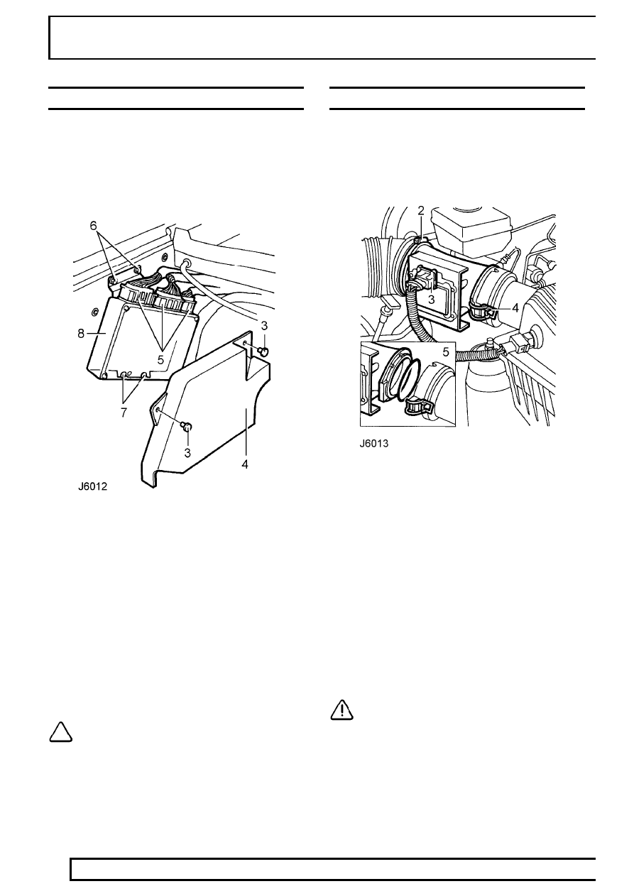
ENGINE CONTROL MODULE (ECM)

Service repair no - 18.30.01

Remove

1. Disconnect battery negative lead.

2. Release and move washer reservoir aside.

See

WIPERS AND WASHERS, Repair, Washer
Reservoir

3. Remove 2 studs securing ECM cover.
4. Remove cover.
5. Disconnect 3 ECM multiplugs.
6. Remove 2 bolts securing ECM.
7. Release ECM from 2 lower retainers.
8. Remove ECM.

Refit

9. Reverse removal procedure.

NOTE: Ensure ECM is correctly located by
lower retainers.

MASS AIR FLOW SENSOR (MAF SENSOR)

Service repair no - 19.22.25

Remove

1. Disconnect battery negative lead.

2. Loosen clip and disconnect intake hose from

MAF sensor.

3. Disconnect multiplug from MAF sensor.
4. Release 2 clips and remove MAF sensor from air

cleaner.

5. Collect ’O’ ring seal.

Refit

6. Ensure mating faces of air cleaner, MAF sensor

and intake hose are clean.

7. Fit ’O’ ring to MAF sensor.
8. Fit MAF sensor to air cleaner and secure with

clips.

9. Connect multiplug to MAF sensor.

10. Connect intake hose and secure with clip.

CAUTION: Failure to connect intake hose
securely will allow unmetered air to enter
the engine, causing running problems.

11. Reconnect battery negative lead.

SFI

5

REPAIR

FUEL RAIL AND INJECTORS

Service repair no - 19.60.04 - Fuel Rail
Service repair no - 19.60.12 - Injectors

Remove

1. Disconnect battery negative lead.
2. Depressurise fuel system.

See Fuel System -

Depressurise

3. Release plenum chamber and place aside.

See

Plenum Chamber

4. Disconnect purge hose, crankcase breather

hose, servo vacuum hose and fuel regulator
hose from ram housing.

5. Remove 6 bolts securing ram housing to inlet

manifold.

6. Place small packing block on inlet manifold.

Lever between packing block and ram pipe
housing to break seal.

CAUTION: Do not lever against fuel rail.

7. Remove ram housing.
8. Place cloth over inlet manifold to prevent ingress

of foreign matter.

9. Disconnect 8 injector multiplugs.

10. Disconnect fuel temperature sensor multiplug.
11. Position cloth around fuel feed pipe union to

absorb fuel spillage.

12. Disconnect fuel feed pipe from fuel rail.
13. Plug fuel pipe and rail.
14. Slacken clip securing fuel return hose.

19

FUEL SYSTEM

6

REPAIR

15. Disconnect hose, plug return hose and rail.

Remove cloth.

16. Remove 6 nuts securing fuel rail and ignition coil

bracket to inlet manifold.

17. Release ignition coil bracket from inlet manifold

studs. Place aside.

18. Release fuel rail and injectors from inlet

manifold.

Do not carry out further dismantling if component
is removed for access only.

19. Remove fuel rail and injectors.

20. Remove 2 bolts securing fuel pressure regulator

to fuel rail.

21. Remove pressure regulator assembly.
22. Remove ’O’ ring from fuel pressure regulator and

discard.

23. Remove 8 clips securing injectors to fuel rail.
24. Remove injectors from fuel rail.
25. Remove 2 ’O’ rings from each injector and

discard.

Refit

26. Ensure mating surfaces between inlet manifold

and ram pipe housing are clean.

27. Ensure all locations in fuel rail and inlet manifold

are clean.

28. Lubricate and fit new ’O’ rings to injectors and

fuel pressure regulator.

29. Fit fuel pressure regulator to fuel rail. Secure

with bolts. Tighten to

10 Nm.

30. Fit injectors to fuel rail. Secure with clips.
31. Position fuel rail to inlet manifold. Engage

injectors, one bank at a time.

32. Position ignition coil bracket on inlet manifold

studs.

33. Secure ignition coil bracket and fuel rail to inlet

manifold with nuts. Tighten to

8 Nm.

34. Remove plugs from fuel feed and return pipes

and rail.

35. Connect hose and tighten clip.
36. Clean feed pipe union and connect fuel feed

pipe to fuel rail. Tighten union to

16 Nm.

37. Connect multiplugs to fuel injectors and fuel

temperature sensor.

38. Remove cloth from inlet manifold.
39. Apply a thin, uniform coating of Loctite 577

sealant to mating face of inlet manifold.

40. Fit ram housing to inlet manifold. Secure with

bolts. Tighten to

24 Nm.

41. Connect purge hose, crankcase breather hose,

servo and pressure regulator vacuum hoses to
ram housing.

42. Fit plenum chamber.

See Plenum Chamber

43. Reconnect battery negative lead.
44. Start engine. Check for leaks around fuel rail and

injectors.

SFI

7

REPAIR

FUEL TEMPERATURE SENSOR

Service repair no - 19.22.08

Remove

NOTE: Because fuel leakage will not occur
when sensor is removed, it is not
necessary to depressurise the fuel system

for this operation.

1. Disconnect battery negative lead.

2. Disconnect multiplug from fuel temperature

sensor.

3. Remove sensor from fuel rail.

Refit

4. Ensure sensor and location in fuel rail are clean.
5. Fit sensor. Tighten to

17 Nm.

6. Connect multiplug.
7. Reconnect battery negative lead.


Content   ..  70  71  72  73   ..