Land Rover Discovery. Manual - part 63


  Index      Land Rover     Land Rover Discovery - service 1995-1996 year


Search            


Content   ..  61  62  63  64   ..


Land Rover Discovery. Manual - part 63


MFI

5

REPAIR

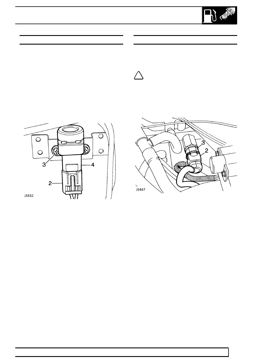
INERTIA FUEL SHUTOFF SWITCH

Service repair no - 18.30.35

The inertia fuel shutoff switch is located on the
bulkhead next to the washer reservoir under bonnet
[hood].

Remove

1. Disconnect battery negative lead.
2. Disconnect multiplug from inertia switch.
3. Remove 2 screws securing inertia switch to

mounting bracket.

4. Remove inertia switch.

Refit

5. Position inertia switch to mounting bracket and

secure with screws.

6. Connect multiplug to inertia switch.
7. Reconnect battery negative lead.

ENGINE FUEL TEMPERATURE SENSOR

Service repair no - 19.22.08

Remove

NOTE: Fuel leakage will not occur when
sensor is removed from fuel rail, therefore
it is not necessary to depressurise the fuel

system.

1. Disconnect battery negative lead.
2. Disconnect multi-plug from sensor.
3. Release sensor from fuel feed rail.

Refit

4. Reverse removal procedure. Ensure sensor is

tightened securely in fuel rail.

19

FUEL SYSTEM

6

REPAIR

ENGINE COOLANT TEMPERATURE SENSOR

Service repair no - 19.22.18

Remove

1. Position drain tray to collect coolant spillage.
2. Disconnect multiplug from coolant sensor.
3. Remove sensor from thermostat housing.
4. Remove and discard copper washer.

Refit

5. Fit a new copper washer.
6. Fit sensor and tigten securely.
7. Top-up cooling system.
8. Run engine, check for water leaks around

sensor.

DEPRESSURISING FUEL SYSTEM

WARNING: Under normal operating
conditions the Multiport fuel injection
system is pressurised by a high pressure

fuel pump, operating at up to 2.3 to 2.5 bar When
engine is stationary pressure is maintained within
system. To prevent pressurised fuel escaping and
to avoid personal injury it is necessary to
depressurise multiport fuel injection system
before any service operations are carried out.

If vehicle has not been run there will be a small
amount of residual pressure in fuel line. The
depressurising procedure must still be carried out
before disconnecting any component within the
fuel system.

The spilling of fuel is unavoidable during this
operation. Ensure that all necessary precautions
are taken to prevent fire and explosion.

1. Remove fuel pump relay module.

See

Multiport Fuel Injection Relays

2. Start and run engine.
3. When sufficient fuel has been used to cause fuel

line pressure to drop, injectors will become
inoperative, resulting in engine stall. Switch off
ignition.

4. Disconnect battery negative lead.

NOTE: Fuel at low pressure will remain in
system. To remove low pressure fuel,
place absorbent cloth around fuel feed

hose at fuel rail.

5. Disconnect either:

a) Nut and olive at fuel rail
OR
b) Hose at inlet end of fuel filter.

Refit

6. Refit fuel feed hose.
7. Refit fuel pump relay module, reconnect battery.
8. Crank engine (engine will fire in approximately 6

to 8 seconds).

MFI

7

REPAIR

FUEL PRESSURE REGULATOR

Service repair no - 19.45.06

Remove

1. Depressurise fuel system.

See Depressurising

Fuel System

2. Disconnect battery negative lead.
3. Remove plenum chamber.

See Plenum

Chamber

4. Release clip and disconnect fuel return hose

from regulator.

5. Disconnect vacuum hose from regulator.
6. Remove 2 bolts securing pressure regulator to

fuel rail.

7. Release regulator from fuel rail and withdraw.
8. Remove and discard ’O’ ring.

Refit

9. Lightly coat ’O’ ring with silicon grease 300 and

fit to regulator.

10. Reverse removal procedure.
11. Reconnect battery and pressurise fuel system.

Check there are no fuel leaks around regulator
connections.

FUEL RAIL-INJECTORS R/H AND L/H

Service repair no - 19.60.04 - Rail
Service repair no - 19.60.01 - Injectors

Remove

1. Depressurise fuel system.

See Depressurising

Fuel System

2. Disconnect battery negative lead.
3. Remove plenum chamber.

See Plenum

Chamber

4. Remove ram housing.

See Ram Housing

NOTE: Place cloth over ram tube openings
to prevent ingress of dirt.

5. Loosen clip and disconnect fuel return hose from

regulator.

6. Loosen union and disconnect fuel supply hose

from fuel rail.

7. Disconnect multi-plug from fuel temperature

sensor.

8. Disconnect multi-plugs from injectors.
9. Remove four bolts securing fuel rail support

brackets to intake manifold. Lay injector
harnesses to one side.

19

FUEL SYSTEM

8

REPAIR

10. Remove fuel rail and injectors.
11. Remove injector retaining clips, ease injectors

from rail. Remove and discard ’O’ rings from
injectors.

12. Remove fuel pressure regulator if required.

Refit

13. Fit NEW ’O’ rings, to injectors. Lightly coat ’O’

rings with silicon grease 300. Insert injectors into
fuel rail, multi-plug connections facing outwards.

14. Refit retaining clips.

CAUTION: Care must be taken when
refitting the fuel rail and injectors to intake
manifold to prevent damage to ’O’ rings.

15. Fit a NEW ’O’ ring to pressure regulator lightly

coat ’O’ ring with silicon grease 300 and secure
regulator to the fuel rail.

16. Fit fuel rail and heater pipe assemblies to intake

manifold. Secure rail and pipes in position with
five bolts.

17. Reverse removal procedure. 2 to 7.
18. Pressurise fuel system and check for fuel leaks

around injectors and pressure regulator.

PLENUM CHAMBER

Service repair no - 19.22.46

Includes throttle levers and throttle disc

Remove

1. Disconnect battery negative lead.
2. Disconnect electrical multi-plug from bypass air

valve.

3. Disconnect vacuum hose adjacent to bypass air

valve.

4. Mark an identification line on throttle cable outer

to assist re-assembly.

5. Remove clevis pin from throttle cable.
6. Pry adjustment thumb wheel from throttle

bracket. Lay cable aside.

7. Remove retaining clip and clevis pin from kick

down cable (automatic vehicles).

8. Apply adhesive tape behind rear adjustment nut

on kick down cable to prevent nut moving.

9. Remove front lock nut. Remove cable and lay

aside.

10. Remove cruise control vacuum hose.

11. Remove intake hose from neck of plenum

chamber.

12. Disconnect throttle position sensor multi-plug.
13. Remove PCV breather hose.
14. Disconnect two coolant hoses and plug each

hose to prevent excessive loss of coolant.
Identify each hose for re-assembly.


Content   ..  61  62  63  64   ..