Land Rover Discovery. Manual - part 52
19
FUEL SYSTEM
2
DESCRIPTION AND OPERATION
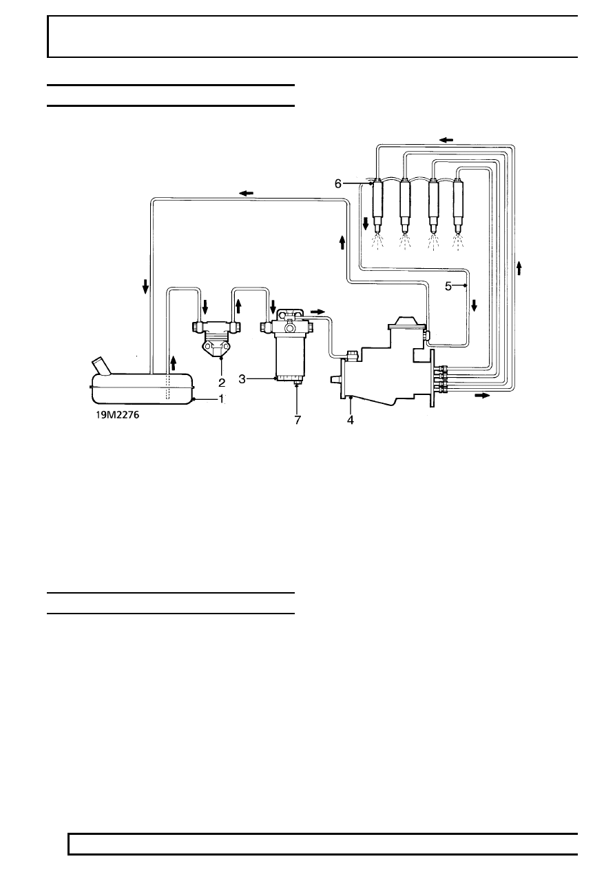
FUEL SYSTEM LAYOUT
1. Fuel tank
2. Fuel lift pump
3. Fuel filter
4. Fuel injection pump
5. Spill return line
6. Fuel injectors
7. Sediment plug
FUEL SYSTEM COMPONENT LOCATION
1. Fuel filter bleed screw
2. Fuel filter
3. Turbocharger
4. Wastegate
5. Air cleaner
6. Fuel injector
7. Glow plug
8. Glow plug controller
9. EGR valve and valve lift position sensor
10. Coolant temperature transmitter - EGR and instruments
11. Fuel injection pump
12. EGR throttle position sensor
13. Fuel lift pump
14. Intercooler
15. EGR Control unit