Land Rover Discovery. Manual - part 31


  Index      Land Rover     Land Rover Discovery - service 1995-1996 year


Search            


Content   ..  29  30  31  32   ..


Land Rover Discovery. Manual - part 31


V8i

5

REPAIR

CYLINDER HEADS - RENEW

Service repair no - 12.29.15

1. Remove cylinder heads and gaskets.

See

Cylinder Head Gaskets - Renew

2. Remove spark plugs.
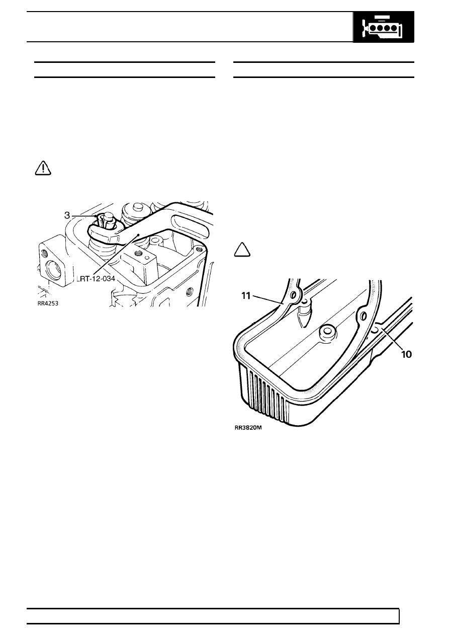
3. Using spring compressor LRT-12-034, remove

seals, valves, collets, springs and caps.

CAUTION: Keep components in fitted
order

4. From left hand cylinder head, remove earth lead

studs.

5. Remove three bolts securing power steering

pump mounting bracket to cylinder head.

6. Remove four bolts securing generator mounting

bracket to cylinder head.

7. Right hand cylinder head, remove rear lifting

bracket.

8. Fit lifting bracket to new right hand cylinder

head.

9. Fit mounting brackets and earth lead studs to

new cylinder head. Tighten bolts to

30 Nm.

10. Regrind valves- refer to engine overhaul

publication

11. Lubricate valve stems, fit valves, springs, and

caps. Fit new inlet and exhaust valve stem seals.

12. Using spring compressor LRT-12-034, compress

springs, fit collets. Tap valve to check correct
collet seating.

13. Fit spark plugs.
14. Fit cylinder heads with new gaskets.

See

Cylinder Head Gaskets - Renew

ROCKER COVER - RIGHT HAND - RENEW

Service repair no - 12.29.41

1. Disconnect battery negative lead.
2. Disconnect purge pipe from charcoal canister at

plenum.

3. Remove breather pipe from rocker cover.
4. Remove coolant pipes from inlet manifold.
5. Remove spark plug leads from plugs and

retaining clips.

6. Remove four rocker cover bolts. Moving fuel

pipes aside, remove rocker cover.

7. Discard rocker cover gasket.
8. Remove plug lead retaining clips from rocker

cover, fit to new rocker cover.

9. Clean and dry rocker cover and cylinder head

mating faces, using Bostik cleaner 6001.

NOTE: Gasket fits one way round only. It
must be fitted accurately, first time.
Subsequent movement will destroy

bonding.

10. Apply Bostik 1775 impact adhesive to rocker

cover seal face and gasket, using a brush to
ensure an even film. Allow adhesive to become
touch dry.

12

ENGINE

6

REPAIR

11. Place one end of gasket into cover recess with

edge firmly against recess wall, holding
remainder of gasket clear. Work around cover,
pressing gasket into place ensuring edge firmly
contacts recess wall.

12. Allow cover to stand for thirty minutes before

fitting.

13. Fit rocker cover to cylinder head with four

screws, short screws inboard, tighten to

9 Nm.

14. Position fuel pipes.
15. Fit breather pipe to rocker cover, tighten clip.
16. Fit coolant pipes to inlet manifold, tighten bolts.
17. Fit spark plug leads to plugs and retaining clips.
18. Connect purge pipe from charcoal canister at

plenum, tighten clip.

ROCKER COVER - LEFT HAND - RENEW

Service repair no - 12.29.40

1. Remove air flow sensor.

See FUEL SYSTEM,

Repair, Air Flow Sensor

2. Remove plenum chamber.

See FUEL SYSTEM,

Repair, Plenum Chamber

3. Remove dipstick.
4. Remove spark plug leads from plugs and

retaining clips.

5. Disconnect HT lead from coil.
6. Remove generator heat shield securing nut from

rocker cover.

7. Remove air flow meter harness clip.
8. Remove bolt securing dipstick tube clip.
9. Remove four rocker cover bolts, remove rocker

cover.

10. Discard gasket
11. Remove plug lead retaining clips from rocker

cover, fit to new rocker cover.

12. Clean and dry rocker cover and cylinder head

mating faces, using Bostik cleaner 6001.

NOTE: Gasket fits one way round only. It
must be fitted accurately, first time.
Subsequent movement will destroy

bonding.

13. Apply Bostik 1775 impact adhesive to rocker

cover seal face and gasket, using a brush to
ensure an even film. Allow adhesive to become
touch dry, approximately fifteen minutes.

14. Place one end of gasket into cover recess with

edge firmly against recess wall, holding
remainder of gasket clear. Work around cover,
pressing gasket into place ensuring edge firmly
contacts recess wall.

15. Allow cover to stand for thirty minutes before

fitting.

16. Fit rocker cover to cylinder head with four

screws, short screws inboard. Tighten to

9 Nm.

17. Position dipstick tube clip. Fit and tighten bolts.
18. Fit and tighten air flow meter harness clip.
19. Fit generator heat shield to rocker cover.
20. Connect HT lead to coil.
21. Connect spark plug leads to plugs and retaining

clips.

22. Fit dipstick.
23. Fit plenum chamber.
24. Fit air flow meter.

V8i

7

REPAIR

ROCKER SHAFT RENEW

Service repair no - 12.29.29

1. Remove rocker covers as required.

See

Rocker Cover - Right Hand - Renew or. See
Rocker Cover - Left Hand - Renew

2. Loosen four rocker shaft fixings.

3. Remove rocker shaft assembly.

NOTE: Each rocker shaft is notched at
ONE end. Notch must be uppermost and
towards front of engine on right hand side,

towards rear on left hand side.

4. Clean rocker pedestal locations on cylinder

head.

5. Fit rocker shaft assembly, locating push rods to

rockers.

6. Tighten rocker shaft fixings to

38 Nm.

7. Fit rocker covers.

HYDRAULIC TAPPETS RENEW

Service repair no - 12.29.57

1. Remove rocker shafts.

See Rocker Shaft

Renew

2. Remove intake manifold.

See FUEL SYSTEM,

Repair, Intake Manifold

3. Remove push rods, retain in removal sequence.

4. Remove hydraulic tappets
5. Fit tappets, push rods and rocker assemblies.

See V8i Overhaul Manual.

6. Fit inlet manifold.
7. Reverse removal procedure.

12

ENGINE

8

REPAIR

CRANKSHAFT PULLEY ASSEMBLY

Service repair no - 12.21.01

1. Remove viscous coupling.

See COOLING

SYSTEM, Repair, Viscous Coupling, Fan
Blades, Pulley and Fan Cowl

2. Remove drive belt.

See Drive Belt

3. Raise vehicle on ramp [hoist].
4. Remove bell housing bottom cover.
5. Remove engine undertray.
6. With assistance to stop flywheel rotation, remove

crankshaft pulley assembly retaining bolt.

7. Remove crankshaft pulley assembly.
8. If required: Place assembly in vice and remove

pulley.

9. Fit pulley to torsional vibration damper.

10. Lubricate seal face of assembly.
11. Fit pulley assembly.
12. With assistance to stop flywheel rotation, fit

retaining bolt. Tighten to

280 Nm.

13. Reverse removal procedure. 1 to 5.

FRONT COVER OIL SEAL - RENEW

Service repair no - 12.21.14

1. Remove crankshaft pulley.

See Crankshaft

Pulley Assembly. Do not remove pulleys.

2. Remove eight screws and remove mud

excluder.

3. Fit button of 18G1328 to crankshaft, fit extractor

to seal.

4. Turn centre bolt of extractor to remove seal.
5. Remove seal from extractor.
6. Clean seal seating.
7. Lubricate outside diameter of seal.
8. Locate seal in front cover.
9. Fit adaptor 18G1291/5 to 18G1291/4.

10. Fit tool to seal.
11. Fit and tighten centre bolt to crankshaft, tighten

centre locknut to seat seal.

12. Slacken locknut and remove tool.
13. Lubricate seal lip.
14. Fit mud excluder and tighten screws.
15. Fit crankshaft pulley assembly.


Content   ..  29  30  31  32   ..