Land Rover Discovery. Manual - part 23


  Index      Land Rover     Land Rover Discovery - service 1995-1996 year


Search            


Content   ..  21  22  23  24   ..


Land Rover Discovery. Manual - part 23


12

ENGINE

10

REPAIR

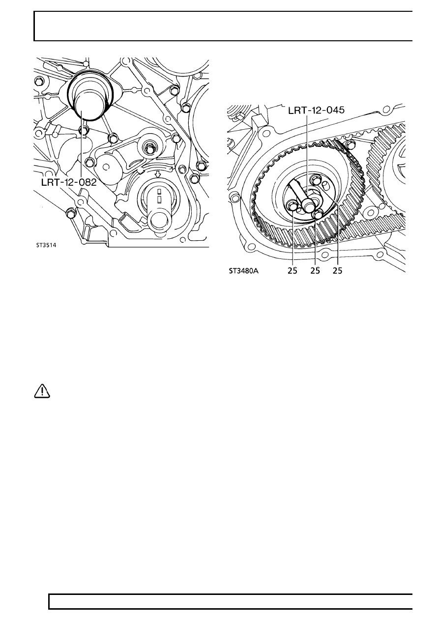
21. With lip side leading, drive-in seal squarely using

special tool LRT-12-082.

22. Refit gear.

FUEL INJECTION PUMP GEAR
Service repair no - 19.30.06

Remove

23. Slacken the three bolts on front of gear.

CAUTION: It is important to ensure that
when the injection pump is locked no
attempt must be made to rotate it. Take

care not to allow the crankshaft to be turned.

24. Remove special tool pin from gear.
25. Remove three bolts and withdraw plate and

gear.

Refit

26. Fit gear and plate and secure with three bolts.
27. Insert pin from special tool LRT-12-045 in

injection pump gear and through into pump
flange.

Tdi

11

REPAIR

Timing belt fitting and tensioning

NOTE: It is important that belt tensioning
is carried out carefully and accurately. The
following procedure involves tensioning

the belt twice to ensure that it is equally tensioned
between each gear. New and original belts are
tensioned to different figures.

28. Ensure timing marks are correctly aligned, pin

from special tool LRT-12-045 is correctly
inserted in injection pump gear and timing tool
LRT-12-044 (LRT-12-085 if EDC) is fitted to
flywheel housing with pin located in flywheel slot.
Or if automatic: Timing tool LRT-12-044 is fitted
to engine backplate and pin located in ring gear.

29. Fit belt observing rotational marks made during

removal. Feed belt over gears keeping it tight on
drive side.

30. Fit idler pulley.
31. Slacken injection pump gear retaining bolts.
32. Adjust belt to correctly sit in gears.

33. Slacken belt tensioner securing bolt to finger

tight.

34. Insert 13 mm square drive extension bar in

tensioner plate.

NOTE: Belt tensioning should be carried
out using a dial type torque meter having a
range not exceeding

60 Nm. The torque

meter should be used in the almost vertical
position.

35. Apply a tension of

14 to 16 Nm for a new belt or

11 to 13 Nm for an original belt. When tension
is correct tighten clamp bolt.

36. Tighten injection pump gear bolts.
37. Remove pin from injection pump gear.
38. Disengage timing pin from timing slot in flywheel

or ring gear.

39. Rotate crankshaft one and three quarter turns in

a clockwise direction; then continue rotation until
timing pin in timing tool can be engaged with slot
in flywheel or ring gear.

40. Disengage timing pin.
41. Insert pin from special tool LRT-12-045 in

injection pump gear and through into pump
flange.

42. Slacken injection pump gear retaining bolts.
43. Slacken tensioner and retension belt.
44. Tighten injection pump gear retaining bolts.
45. Remove pin from injection pump gear.
46. Remove timing tool and refit plug.
47. Fit front cover plate using new gaskets.

See

Front Cover Plate

12

ENGINE

12

REPAIR

FRONT COVER/TIMING GEAR HOUSING GASKET

Service repair no - 12.65.10

Remove

1. Remove timing belt and gears.

See Camshaft

Drive Belt and Gears

2. Remove fuel injection pump.

See FUEL

SYSTEM, Repair, Fuel Injection Pump and
Timing

3. Remove engine oil sump.

See Oil Sump

4. Remove oil pick up strainer.

See Oil Pick-Up

Strainer

5. Remove bolts securing timing gear housing to

block.

6. Withdraw timing gear housing complete with

gasket.

7. Clean all gasket material from mating faces.

Refit

8. Fit slave guide studs to locate gasket.
9. Fit new gasket, over slave studs, to cylinder

block.

10. Align flats on oil pump with flats on crankshaft.
11. Fit front cover to block taking care not to damage

oil seal.

12. Secure with bolts of correct length in locations

where slave studs are not fitted (ST3482).

13. Remove slave studs and fit correct length bolts.
14. Tighten to

25 Nm.

15. Fit oil pick-up strainer.

See Oil Pick-Up

Strainer

16. Fit oil sump.

See Oil Sump

17. Refit fuel injection pump.

See FUEL SYSTEM,

Repair, Fuel Injection Pump and Timing

Tdi

13

REPAIR

OIL SUMP

Service repair no - 12.60.44

Remove

1. Disconnect battery negative lead.
2. Drain engine oil.
3. Slacken sump securing bolts and, using a sharp

knife, break sealant around sump flange.

4. Remove bolts and withdraw sump.

Refit

5. Clean mating faces of sump, timing gear housing

and cylinder block.

6. Apply a 2,0 mm bead of ’Hylosil RTV102’ to the

sump flange, ensuring bead is applied inboard of
the bolt holes.

7. Secure sump to block with bolts. Tighten to

25

Nm.

8. Refill engine oil.

See LUBRICANTS, FLUIDS

AND CAPACITIES, Information,
Recommended Lubricants and Fluids

9. Reconnect battery negative lead.

OIL PICK-UP STRAINER

Service repair no - 12.60.20

Remove

1. Disconnect battery negative lead.
2. Drain engine oil.
3. Remove engine oil sump.

See Oil Sump

4. Remove bolts securing pipe support bracket.
5. Remove bolts from pipe flanges.
6. Withdraw pick-up strainer assembly.

Refit

7. Refit pick-up strainer assembly, fitting a new ’O’

ring seal at oil pump connection.

8. Apply Loctite 242E to the two screws at the

bearing cap. Tighten to

9 Nm.

9. Fit bolts to pipe flanges. Tighten to

25 Nm.

10. Refit engine oil sump.

See Oil Sump

11. Reconnect battery negative lead.


Content   ..  21  22  23  24   ..