Defender 300Tdi (1996+). Manual - part 105


  Index      Land Rover     Defender 300Tdi - service repair manual 1996 year


Search            


Content   ..  103  104  105  106   ..


Defender 300Tdi (1996+). Manual - part 105


ELECTRICAL

1

FAULT DIAGNOSIS

GENERAL INFORMATION

Detailed information of electrical systems, component
locations and circuit diagrams are covered in the
Defender Electrical Troubleshooting Manual.

This section covers checks of the charging system.

GENERATOR TESTING

Service repair no - 86.10.01

Charging system check

1. Check battery is in good condition, with an open

circuit voltage of at least 12.6 V. Recharge or
substitute battery to carry out test.

2. Check drive belt condition

See SECTION 10,

Maintenance, Under bonnet maintenance.

3. Check battery connections are clean and tight.
4. Check generator connections are clean and

tight.

5. Ensure there is no drain on battery from, for

example, interior or exteriorlamps.

Generator test

Following instructions refer to use of suitable test
equipment using a carbon pile rheostat.

6. Connect test equipment referring to

manufacturer’s instructions.

7. Start engine and run at 3000 rev/min without

accessory load.

8. Rotate carbon pile load control to achieve

greatest output (amps) without allowing voltage
to fall below 12.0 V. A reading in amps, of
generator output should be obtained.

9. Run engine at 3000 rev/min, switch selector to

regulator test, read voltmeter. A reading of 13.6
to 14.4 V should be obtained.

10. Switch selector to diode/stator test, switch on

headlamps to load generator. Raise engine
speed to 3000 rev/min, read voltmeter, needle
must be within ’OK’ range.
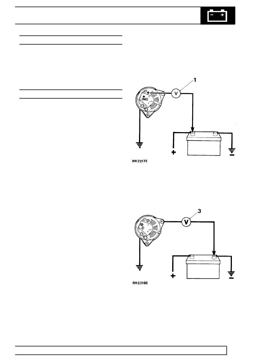
TESTING IN POSITION

Charging circuit resistance test.

1. Connect a low range voltmeter between

generator terminal marked B+ and positive
terminal of battery.

2. Switch on headlamps, start engine. Run engine

at approximately 3000 rev/min. Note voltmeter
reading.

3. Transfer voltmeter connections to frame of

generator and negative terminal of battery, and
again note voltmeter reading.

4. If reading exceeds 0.5 volt on positive side or

0.25 volt on negative side, there is a high
resistance in charging circuit which must be
traced and remedied.

ELECTRICAL

1

REPAIR

ELECTRICAL PRECAUTIONS

The following guidelines are intended to ensure the
safety of the operator whilst preventing damage to
electrical and electronic components fitted to the
vehicle.

Polarity

Never reverse connect the vehicle battery and always
observe the correct polarity when connecting test
equipment.

High voltage circuits

WARNING: Before commencing work on
an ignition system, all high tension
terminals, adaptors and diagnostic

equipment for testing should be inspected to
ensure that they are adequately insulated and
shielded to prevent accidental personal contacts
and minimize the risk of shock. Wearers of
surgically implanted pacemaker devices should
not be in close proximity to ignition circuits or
diagnostic equipment.

Whenever disconnecting live high tension circuits
always use insulated pliers and never allow the open
end of a high tension lead to come into contact with
other components particularly electronic control units.
Exercise caution when measuring the voltage on the
coil terminals while the engine is running, since, high
voltage spikes can occur on these terminals.

Connectors and harness

Always ensure that these items are dry and oil free
before disconnecting and connecting test equipment.
Never force connectors apart either by using tools or
by pulling on the wiring harness. Always ensure
locking tabs are disengaged before removal and note
orientation to enable correct reconnection. Ensure that
any protective covers and substances are replaced if
disturbed. Having confirmed a component to be faulty
switch-off the ignition and disconnect the battery.
Remove the component and support the disconnected
harness. When replacing the component keep oily
hands away from electrical connection areas and
push connectors home until any locking tabs fully
engage.

Battery disconnecting

Before disconnecting the battery, switch off all
electrical equipment.

Battery charging

Recharge the battery out of the vehicle and keep the
top well ventilated. While being charged or
discharged, and for approximately 15 minutes
afterwards, batteries emit hydrogen gas which is
flammable. Always ensure any battery charging area
is well ventilated and that every precaution is taken to
avoid naked flames and sparks.

GENERAL PRECAUTIONS

Switch-off ignition prior to making any connection or
disconnection in the system as electrical surge
caused by disconnecting ’live’ connections can
damage electronic components.

Ensure hands and work surfaces are clean and free of
grease, swarf, etc. as grease collects dirt which can
cause tracking or high-resistance contacts.

When handling printed circuit boards, treat them as
you would a disc - hold by the edges only.

Prior to commencing a test, and periodically during a
test, touch a good earth, for instance, a cigar lighter
socket, to discharge body static as some electronic
components are vulnerable to static electricity.

86

ELECTRICAL

2

REPAIR

BATTERY

Service repair no - 86.15.01

NOTE: If the vehicle is fitted with a battery
backed-up alarm sounder, disconnecting
the vehicle battery will cause the alarm to

sound unless the following procedure is followed:

1. Remove LH front seat cushion.
2. Release retaining clip and remove battery

access cover.

3. Slacken battery negative lead clamp bolt.
4. Turn starter switch ’on’.
5. Turn starter switch ’off’ and remove key.
6. Disconnect battery WITHIN 15 SECONDS.

If alarm is accidentally activated, ensure sounder is
connected and silence by turning the starter switch to
position ’II’.

Remove

WARNING: During battery removal or
before carrying out any repairs or
maintenance to electrical components

always disconnect negative lead first. If positive
lead is disconnected with negative lead in place,
accidental contact of a wrench to any grounded
metal part could cause a severe spark, possibly
resulting in personal injury. Upon installation of
battery always connect positive lead first.

1. Remove LH front seat cushion.
2. Release retaining clip and remove battery

access cover.

3. Disconnect both battery leads, negative first.
4. Slacken securing nuts and move battery clamp,

with ’J’ bolts aside.

5. Remove battery.

NOTE: Coat battery clamps and terminals
with petroleum jelly before refitting.

Refit

6. Position battery and secure with clamp. Ensure

’J’ bolts are hooked correctly under retaining
brackets on base of battery box.

7. Reconnect battery leads, positive lead first.
8. Fit battery access cover.
9. Fit seat cushion.

ELECTRICAL

3

REPAIR

ELECTRONIC CONTROL UNIT (ECU)

Service repair no - 86.55.85

Remove

1. Remove LH front seat cushion.
2. Release retaining clip and remove battery

access cover.

3. Slacken battery negative lead clamp bolt.
4. Turn starter switch ’on’.
5. Turn starter switch ’off’ and remove key.
6. Disconnect battery negative lead.

NOTE: Operation 6 needs to be carried out
within 15 seconds to avoid activating
battery backed-up alarm sounder, if fitted.

7. Remove steering wheel

See STEERING,

Repair, Steering wheel.

8. Remove 4 screws securing instrument panel to

fascia cowl

See INSTRUMENTS, Repair,

Instrument panel.

9. Pull instrument panel away from fascia cowl and

disconnect speedometer cable, multi-plugs,
alarm LED plug lead, heated rear screen lead,
gearbox oil temperature lead and immobiliser
warning light leads.

10. Remove instrument panel.
11. Remove 2 screws securing ECU to fascia cowl

(LH drive shown). On RH drive vehicles ECU is
positioned lower down, on vertical face of fascia
panel.

12. Release ECU from fascia cowl and disconnect

both multi-plugs.

13. Remove ECU.

NOTE: A new ECU must be initialised
using TestBook.

Refit

14. Position ECU at fascia cowl and reconnect both

multi-plugs.

15. Locate ECU on mounting face of fascia cowl and

secure with 2 screws.

16. Position instrument panel to fascia cowl and

reconnect immobiliser warning light leads,
gearbox oil temperature lead, heated rear screen
lead, alarm LED plug lead, multi-plugs and
speedometer cable.

17. Secure instrument panel to fascia cowl with 4

screws

See INSTRUMENTS, Repair,

Instrument panel.

18. Fit steering wheel

See STEERING, Repair,

Steering wheel.

19. Reconnect battery negative lead.
20. Fit battery access cover.
21. Fit LH seat cushion.


Content   ..  103  104  105  106   ..