Defender 300Tdi (1996+). Manual - part 88


  Index      Land Rover     Defender 300Tdi - service repair manual 1996 year


Search            


Content   ..  86  87  88  89   ..


Defender 300Tdi (1996+). Manual - part 88


76

CHASSIS AND BODY

36

REPAIR

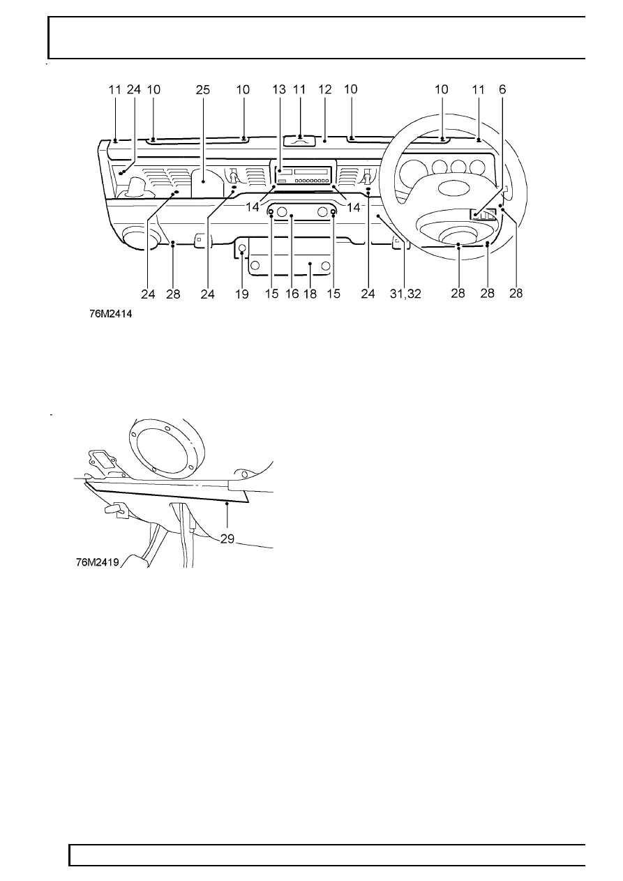
26. Release demist hose and lift parcel shelf from

lower fascia panel (heater duct). Feed main
harness leads and plugs through aperture in
parcel shelf.

27. Remove parcel shelf.

28. Remove 7 screws securing bottom edge of lower

fascia panel to fascia bulkhead, noting position
of both footwell cover retaining plates.

29. Remove both retaining plates and lower footwell

covers.

30. Unscrew 2 retaining bolts securing top edge of

lower fascia panel to bulkhead.

31. With assistance, lower fascia panel and, if

applicable, disconnect RH radio speaker leads.

32. Remove fascia panel from vehicle.

Refit

33. Position lower fascia panel to bulkhead,

reconnect RH speaker leads, if applicable, and
secure top edge with 2 bolts.

34. Locate RH footwell cover retaining plate under

bottom edge of fascia panel and secure with 3
screws.

35. Repeat operation for LH footwell cover retaining

plate.

36. Fit remaining lower fascia panel fixing screws.
37. Locate parcel shelf. Ensure all radio and

auxiliary switch panel harness leads and plugs
are fed through aperture in parcel shelf.

38. Fit demist hoses into heater duct of lower fascia

panel. Ensure flanges of hose grommets are
correctly seated.

39. Fit trim panel and secure with cap fasteners.
40. Reconnect LH speaker leads, if applicable,

locate wiper motor cover pins in lower fascia
panel and secure wth 3 screws. Ensure wiper
rack cover is correctly seated. On LH drive
vehicles, reconnect multi-plugs to rear of switch
panel.

41. Secure finisher to wiper motor cover.
42. Fit door check strap covers on both sides.
43. Fit footwell vents to lower fascia panel.
44. Models fitted with hand throttle:

Fit hand throttle cover.
Secure LH side of fuse box.

45. Fit fuse box cover.
46. Fit auxiliary switch cover to parcel tray, if

applicable.

CHASSIS AND BODY

37

REPAIR

47. Connect leads and plugs to auxiliary switches

and clock.

48. Secure switch panel to lower fascia panel and

switch cover.

49. Position radio housing, if applicable, and feed

radio multi- plug, aerial and speaker leads from
switch cover to radio housing.

50. Secure radio housing to trim panel.
51. Fit radio connections and secure radio in

housing.

52. Fit crash pad to fascia bulkhead.
53. Fit demister vents in crash pad.
54. Fit grab handle to lower fascia panel and secure

to crash pad. Refit Land Rover decal.

55. Connect multi-plugs to rear screen, hazard and

interior lamp switches and fit switch panel to
fascia panel.

56. Fit heater control cable

See HEATING AND

VENTILATION, Repair, Heater control cable -
air distribution 
.

57. Fit instrument panel

See INSTRUMENTS,

Repair, instrument panel .

58. Fit steering column nacelle

See STEERING,

Repair, Steering column nacelle .

59. Fit steering wheel

See STEERING, Repair,

Steering wheel .

60. Reconnect battery.

FRONT UNDERTRAY

Service repair no - 76.11.81 - Front undertray
Service repair no - 76.11.85 - Acoustic pad

Remove

1. Raise vehicle on ramp.
2. Position support under chassis front

crossmember.

3. Lower ramp to give clearance between axle and

undertray.

4. Remove 4 nuts, disconnect propeller shaft from

front axle, and move aside.

5. Remove 2 bolts securing undertray to chassis

front crossmember.

6. Remove nut securing undertray to bump stop

front fixing bolt on both sides.

7. Remove 2 bolts securing sides of undertray to

rear undertray.

8. Pull front undertray forwards to release flanges

from rear undertray.

9. Lower undertray to clear steering box etc. and

manouvre rearwards over axle.

10. Remove front undertray.
11. If necessary, remove 8 fasteners to release

acoustic pad from undertray.

76

CHASSIS AND BODY

38

REPAIR

Refit

12. If applicable, fit acoustic pad to undertray.
13. Fit undertray in position, ensuring flanges are

correctly located in rear undertray.

14. Secure undertray to chassis front crossmember,

bump stops and rear undertray. Tighten fixings
to

14 Nm (10 lbf/ft).

15. Fit propeller shaft to front axle and tighten nuts

to 47 Nm (35 lbf/ft).

16. Raise ramp to remove chassis support.
17. Lower ramp.

REAR UNDERTRAY

Service repair no - 76.11.80 - Rear undertray
Service repair no - 76.11.82 - Acoustic pad

Remove

1. Raise vehicle on ramp.

2. Remove 2 bolts securing sides of undertray to

front undertray.

3. Remove 2 bolts securing rear undertray to

chassis crossmember brackets.

4. Remove bolt securing undertray to RH side of

chassis.

5. Pull undertray rearwards to release from flanges

of front undertray.

6. Remove rear undertray.
7. If necessary, remove 7 fasteners and release

acoustic pad from undertray.

Refit

8. If applicable, fit acoustic pad to undertray.
9. Fit undertray in position, ensuring flanges of front

undertray are correctly located.

10. Secure undertray to chassis crossmember, RH

chassis side, and front undertray. Tighten fixings
to

14 Nm (10 lbf/ft).

11. Lower ramp.

CHASSIS AND BODY

39

REPAIR

ACCESS PANEL - FRONT UNDERTRAY

Service repair no - 76.11.85 - Access panel
Service repair no - 76.11.83 - Acoustic pad

The access panel is provided in the front undertray to
enable fitment of the wading plug into the engine
timing cover.

Remove

1. Raise vehicle on ramp.

2. Remove 5 bolts securing access panel to front

undertray.

3. Remove access panel.
4. If necessary, remove 5 fasteners and release

acoustic pad from access panel.

Refit

5. If applicable, fit acoustic pad to access panel.
6. Fit access panel to front undertray, Tighten

fixings to

14 Nm (10 lbf/ft).

7. Lower ramp.

ACCESS PANEL - REAR UNDERTRAY

Service repair no - 76.11.84

The access panel is provided in the rear undertray to
enable fitment of the wading plug or timing tool
LRT-12-044 in the flywheel housing, and access to
the engine oil sump drain plug.

Remove

1. Raise vehicle on ramp.

2. Rotate access panel anti-clockwise to release

locking flanges.

3. Remove access panel from undertray.

Refit

4. Locate access panel flanges in undertray

apertures.

5. Rotate panel clockwise to secure in undertray.
6. Lower ramp.


Content   ..  86  87  88  89   ..