Defender 300Tdi (1996+). Manual - part 58
57
STEERING
2
ADJUSTMENT
STEERING LOCK STOPS
Service repair no - 57.65.03
Check
1. Measure clearance between tyre wall and radius
arm at full lock. This must be not less than 20
mm.
Adjust
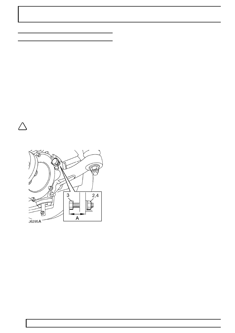
2. Loosen stop bolt locknut.
3. Turn stop bolt as required.
4. Tighten locknut.
5. Check clearance between tyre wall and radius
arm on each lock.
NOTE: Alternatively lock stop adjustment
may be carried out using following
procedure.
Check
1. Measure stop bolt protrusion ’A’. Refer to table
for correct setting.
Adjust
2. Loosen stop bolt locknut.
3. Turn stop bolt as required.
4. Tighten locknut.
5. Check wheel position at full lock.
LOCK STOP SETTINGS
Tyre & wheel size - alloys
Make
Size
Setting
BF Goodrich Mud Terrain
265
59,7 mm
Goodyear GT+4
235
55,7 mm
Michelin M+S 4x4
235
54,2 mm
Tyre & wheel size - steel
Make
Size
Setting
Goodyear
205
52,2 mm
Michelin
205
52,2 mm
Avon
7.50
56 mm
Michelin
7.50
56 mm
Goodyear
7.50
56 mm