Defender 300Tdi (1996+). Manual - part 30


  Index      Land Rover     Defender 300Tdi - service repair manual 1996 year


Search            


Content   ..  28  29  30  31   ..


Defender 300Tdi (1996+). Manual - part 30


26

COOLING SYSTEM

2

DESCRIPTION AND OPERATION

ENGINE (COOLANT) COOLING

Description

The 300Tdi engine uses a pressurised cooling system
and cross flow radiator which is supplied with coolant
from an expansion tank mounted on the RH side of
the engine compartment. A belt driven centrifugal
water pump, fitted to an auxiliary mounting assembly,

pumps coolant to the engine crankcase, cylinder head
and vehicle heater unit.

An eleven bladed fan, incorporating a viscous
coupling, is driven by an independent pulley secured
to the front cover plate. The thermostat housing,
bolted to the front of the cylinder head, is fitted with a
vent valve that purges excessive air pressure and
coolant back to the expansion tank.

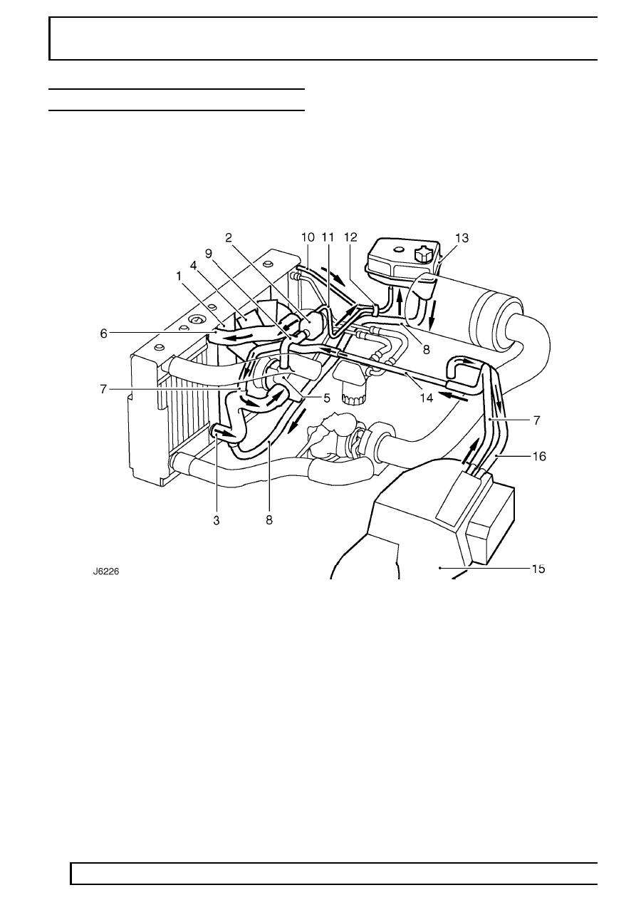
Engine coolant circulation (engine warm - thermostat open).

1. Radiator
2. Thermostat/housing
3. Radiator bottom hose
4. Viscous fan
5. Water pump
6. Radiator top hose
7. Heater return hose
8. Coolant supply hose

9. By-pass hose

10. Radiator bleed (purge) hose
11. Thermostat housing bleed (purge) hose
12. ’Y’ piece ejector
13. Expansion tank
14. Heater rail
15. Heater unit
16. Heater feed hose

COOLING SYSTEM

3

DESCRIPTION AND OPERATION

COOLANT CIRCULATION

Operation

When the engine is started from cold the thermostat
(2) prevents coolant circulation through the radiator by
closing off the top hose (6). During the engine warm
up period the water pump (5) circulates coolant to the
cylinders in the crankcase and through separate ports
to the cylinder head. At the rear of the cylinder head a
proportion of the flow is diverted through a heater feed
pipe (16) to the matrix of the heater unit (15). The
coolant is then carried, via a heater return rail (14) and
hoses (7), back to the water pump. The remaining
coolant flows through a by-pass hose (9) at the
thermostat housing and back to the water pump to
complete the first cycle.

When the normal engine running temperature is
reached, the thermostat opens, closing off the by-pass
hose (9). Coolant is then circulated via the top hose
(6) and through the radiator, where it is cooled and
drawn from the radiator bottom hose (3) by the water
pump (5). The coolant circulation through the
crankcase and cylinder head remains the same.

Two bleed pipes (10) and (11) help control the system
pressure by purging excess air and coolant to the
expansion tank via the ’Y’piece ejector (12).

VISCOUS FAN

Description

The viscous drive unit for the engine cooling fan,
provides a means of controlling the speed of the fan
relative to the running temperature of the engine. The
viscous unit is a type of fluid coupling, which drives
the fan blades by means of ’silicone fluid’.

1. Input (drive) member
2. Output (driven) member
3. Sensing mechanism (bi-metal coil)

The fan drive has to be engaged only periodically,
between 5% and 10%, during normal operating
conditions, because the engine is cooled by ram air
for most of the time.

26

COOLING SYSTEM

4

DESCRIPTION AND OPERATION

Operation

To engage and disengage the fan drive the bi-metal
coil senses air temperature behind the radiator. When
a pre-determined temperature is reached, the coil
opens a valve (5) which allows fluid to enter the drive
area and, due to centrifugal force, circulates to the
annular drive area.

There are two sets of annular grooves (3), one in the
drive clutch and the other in the drive body, a specific
clearance being provided between the two sets of
grooves.

Viscous unit disengaged (engine at normal
running temperature)

1. Input (drive) member
2. Output (driven) member
3. Running clearance
4. Pump plate
5. Valve (closed)
6. Sensing mechanism (bi-metal coil)
7. Fluid seal
8. Bearing, input member
9. Fluid chamber

10. Fluid reservoir

When this clearance is filled with viscous fluid, a
shearing action, caused by the speed differential
between the two drive components, transmits torque
to the fan. The fluid is thrown to the outside of the unit
by centrifugal force from where it is recirculated to the
reservoir (10) via the pump plate (4) adjacent to the
drive member.

If the engine speed is increased the amount of slip will
also increase to limit the maximum fan speed.

When the air temperature from the radiator drops
sufficiently, the bi-metal coil closes the valve and
prevents fluid entering the drive area. The fluid that is
in the drive area will gradually pump out into the
reservoir (10) and the fan will return to an idle
condition.

Viscous unit engaged (hot running temperature)

Bi-metal coil (6) expanded, valve (5) open.

COOLING SYSTEM

1

ADJUSTMENT

DRAIN AND REFILL COOLING SYSTEM

Service repair no - 26.10.01

Draining

WARNING: DO NOT remove caps or plugs
when the engine is hot. The cooling
system is pressurised and personal

scalding could result.

1. Remove expansion tank filler cap.
2. Position a clean container under radiator if

coolant is to be reused.

3. Disconnect radiator bottom hose and allow

coolant to drain.

NOTE: A chassis undertray may be fitted
on some vehicle derivatives to conform to
legal requirements. When under chassis

remove and refit procedures are required, it may
be necessary to remove the undertray and/or
integral access panels.

See CHASSIS AND BODY,

Repair, Front undertray or See CHASSIS AND
BODY, Repair, Rear undertray

4. When expansion tank has emptied remove

thermostat housing plug to assist drainage.

5. Similarly when coolant is below top of radiator,

remove radiator plug.

6. Fit radiator bottom hose and fully tighten hose

clip.

Refill

CAUTION: It is important that the correct
procedure is followed when refilling or
topping up the cooling system to avoid

trapping air in the system.

7. Fill cooling system with 50% - 50% of

water/anti-freeze mixture

See LUBRICANTS,

FLUIDS AND CAPACITIES, Information,
Recommended lubricants and fluids

8. Fill through expansion tank until radiator is full,

with level in expansion tank the same as
radiator.

NOTE: Care should be taken to avoid
excess coolant spillage.

9. Fit plastic plug in radiator.

10. Add a further 1 litre (1.76 pints) of coolant into

expansion tank and allow to settle.

11. Refit expansion tank cap and thermostat

housing plug.

12. Run engine at idle speed for 5 minutes.
13. Switch off engine and allow to cool.
14. Check that coolant in expansion tank is level

with top of indicator post. Top up if necessary.


Content   ..  28  29  30  31   ..