Defender 300Tdi (1996+). Manual - part 24
FUEL SYSTEM
1
ADJUSTMENT
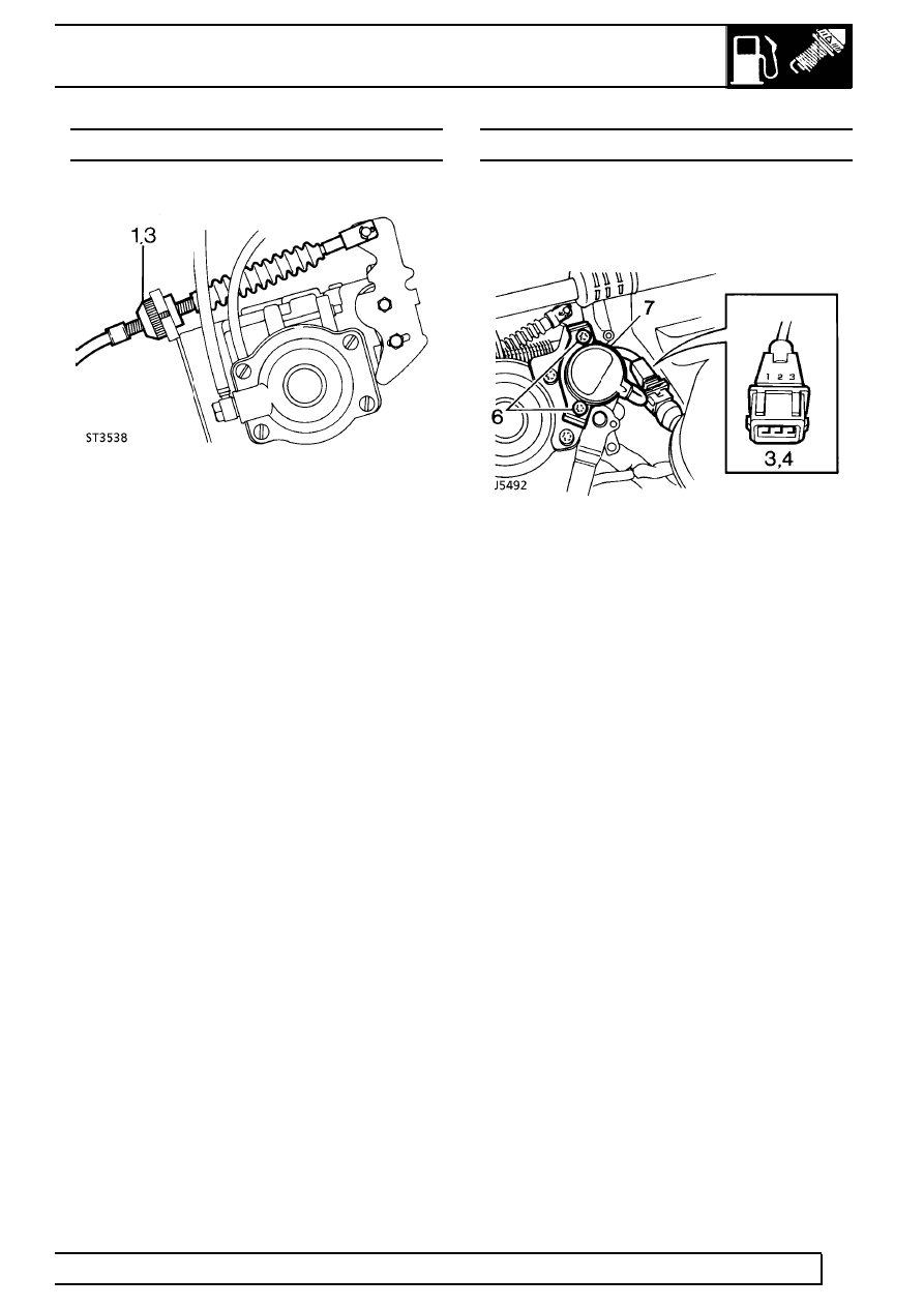
THROTTLE CABLE
Adjust
1. Slacken throttle cable adjustment ferrule.
2. Hold throttle lever in fully closed position.
3. Adjust outer cable, by rotating ferrule, to give
1,57 mm (1/16 in) of deflection in the inner cable.
4. Check that throttle opens fully when the throttle
is depressed.
EGR THROTTLE POSITION SENSOR
Check
1. Run engine until normal operating temperature is
reached.
2. Switch off engine and disconnect throttle position
sensor multi-plug.
3. Connect an Ohmmeter across pins 1 and 3 of
multi-plug. Ohmmeter should read between 1K
and 1.05K ohms.
4. Connect Ohmmeter across pins 1 and 2 of
multi-plug. Ohmmeter should read between 850
and 900 ohms.
5. If readings are correct, reconnect multi-plug.
6. If readings are not obtained slacken 2 torx
screws securing sensor.
7. Rotate sensor to obtain correct Ohmmeter
reading, then tighten torx screws.
8. Re-check readings and fit multiplug.
9. If, after adjustment, Ohmmeter readings cannot
be achieved, fit new sensor.
See Repair, EGR
throttle position sensor