Defender 90 NAS. Manual - part 87


  Index      Land Rover     Defender 90 NAS - service manual 1997 year


Search            


Content   ..  85  86  87  88   ..


Defender 90 NAS. Manual - part 87


HEATING AND VENTILATION

3

REPAIR

Refit

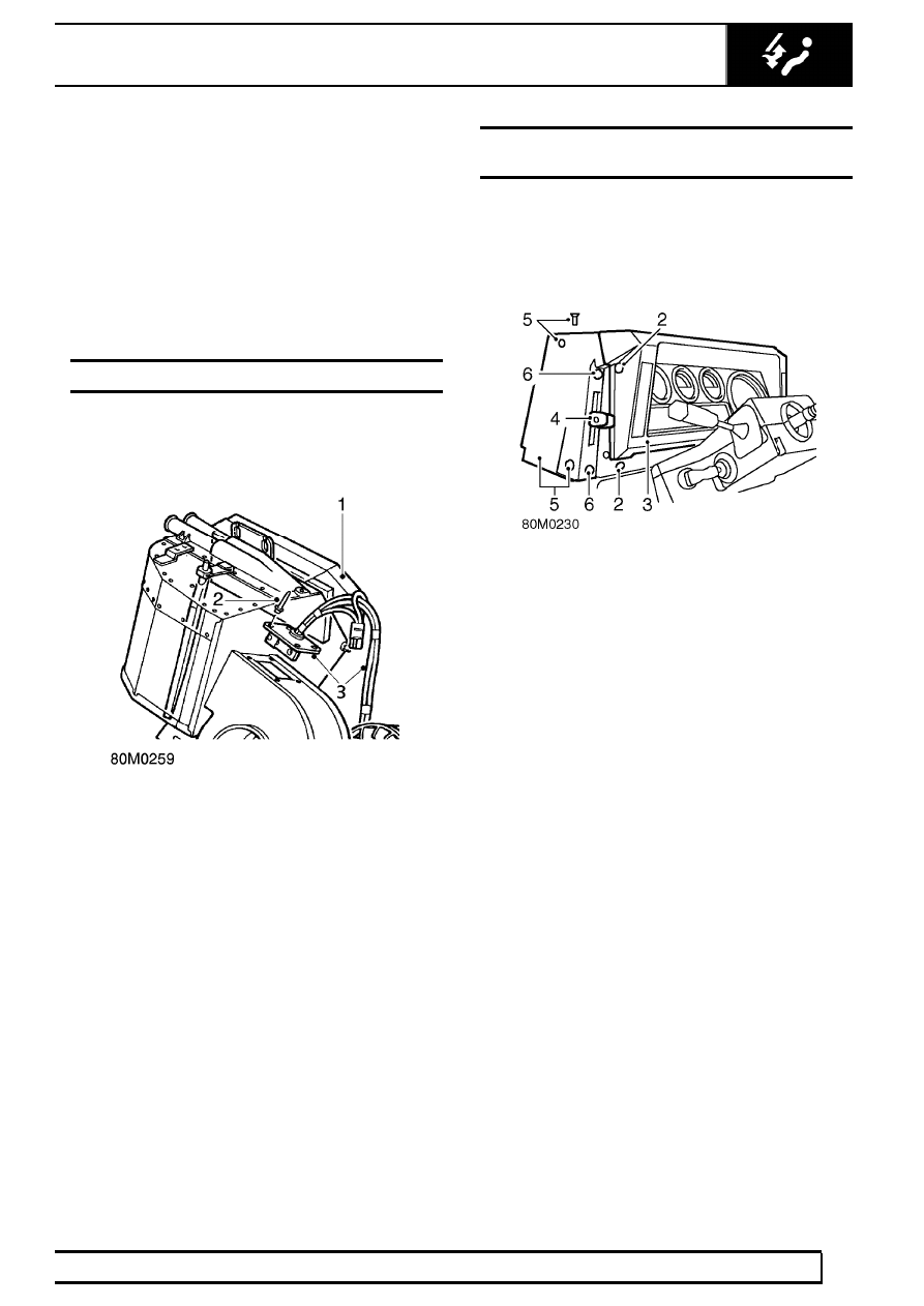
6. Fit foam rubber to heater matrix casing.
7. Position matrix in heater unit casing.
8. Check that both vent flaps operate correctly

without sticking.

9. Secure matrix top retaining plate.

10. Secure matrix bottom retaining plates.
11. Fit heater unit.

See Heater unit

RESISTOR UNIT

Service repair no - 80.20.17

Remove

1. Remove heater unit.

See Heater unit

2. Drill out 4 rivets securing resistor mounting plate

to top of volute housing.

3. Remove resistor and disconnect blower motor

plug from harness.

Refit

4. Apply Bostik adhesive to resistor mounting plate

and rivet to volute housing.

5. Reconnect blower harness motor plug.
6. Fit heater unit.

See Heater unit

HEATER CONTROL CABLE - TEMPERATURE
CONTROL

Service repair no - 80.10.05

Remove

1. Disconnect battery.

2. Remove 4 screws securing instrument binnacle

to fascia cowl.

3. Pull instrument binnacle away from fascia to

ease access to control cable at bulkhead.

4. Remove retaining screws and pull off air

distribution and temperature control lever knobs.

5. Remove 3 screws and detach side cover,

complete with control lever assembly.

80

HEATING AND VENTILATION

4

REPAIR

6. Remove 2 screws securing control lever

assembly to side cover and remove cover.
Retain plastic screw spacers fitted between
cover and control lever assembly.

7. Remove bolt and release outer cable retaining

clip.

8. Slacken grub screw and release inner cable from

clevis.

9. From inside engine compartment: Release outer

cable retaining clip at heater unit.

10. Slacken trunnion fixing and release inner cable

from heater unit flap lever.

11. Release 2 retaining clips securing control cables

to engine bulkhead.

12. Pull control cable through bulkhead grommet

and remove from vehicle.

Refit

13. Fit control cable to heater flap lever trunnion with

approximately 10 mm, 0.4 in of inner cable
protruding from trunnion. Fully tighten trunnion.

14. Secure outer cable with retaining clip.
15. Route control cable through sealing grommet

and along inside of engine bulkhead to fascia
binnacle.

16. Secure control cables to engine bulkhead with

retaining clips.

17. With control lever in closed position, fit inner

cable to lever clevis and fully tighten clevis grub
screw.

18. Fit outer cable retaining clip and fully tighten

securing bolt.

19. Fit side cover to control lever assembly. Ensure

fixing screw spacers are positioned between
cover and lever assembly.

20. Fit side cover to fascia.
21. Fit control lever knobs.
22. Fit instrument binnacle.
23. Reconnect battery.

HEATING AND VENTILATION

5

REPAIR

HEATER CONTROL CABLE - AIR DISTRIBUTION

Service repair no - 80.10.12

Remove

1. Disconnect battery.
2. Remove steering wheel.

3. Remove steering column nacelle.
4. Remove instrument panel.

See

INSTRUMENTS, Repair, Instrument panel

5. Remove retaining screws and pull off air

distribution and temperature control lever knobs.

6. Remove 3 screws and detach side cover,

complete with control lever assembly.

7. Remove 2 screws securing control lever

assembly to side cover and remove cover.
Retain plastic screw spacers fitted between
cover and control lever assembly.

8. Remove bolt and release outer cable retaining

clip.

9. Slacken grub screw and release inner cable from

clevis.

10. Remove heater duct assembly.

See CHASSIS

AND BODY, Repair, Heater duct assembly

11. Remove 19 screws and lift off heater duct cover.
12. Slacken vent flap trunnion fixing, release air

distribution control cable and remove from
heater duct.

13. Check condition of foam sealant on heater duct

cover and renew if necessary.

Refit

14. Fit control cable through heater duct cover and

secure to vent flap trunnion. Bend over cable
end to fully secure.

15. Fit heater duct cover.
16. Fit heater duct assembly to fascia bulkhead.

See CHASSIS AND BODY, Repair, Heater
duct assembly

17. Route control cable along fascia bulkhead to

contol lever assembly.

18. With control lever in closed position, secure

cable to clevis.

19. Fit outer cable retaining clip to lever assembly.
20. Fit lever assembly to side cover. Ensure screw

spacers are fitted between cover and lever
assembly.

21. Fit side cover to fascia cowl.
22. Fit control lever knobs.
23. Fit instrument panel.

See INSTRUMENTS,

Repair, Instrument panel

24. Fit steering column nacelle.

80

HEATING AND VENTILATION

6

REPAIR

CONTROL CABLE AND BLOWER MOTOR SWITCH

Service repair no - 80.10.17 - Control cable
Service repair no - 80.10.22 - Blower motor switch

Remove

1. Disconnect battery.

2. From inside engine compartment, release outer

cable retaining clip at heater unit.

3. Slacken trunnion fixing and release inner cable

from heater unit flap lever.

4. Release 2 retaining clips securing control cables

to engine bulkhead and heater hoses.

5. Remove 4 screws securing instrument panel to

fascia cowl.

6. Pull instrument binnacle away from fascia to

ease access to control cable.

7. Remove 2 screws securing control lever

assembly to side of fascia binnacle cowl. Retain
plastic screw spacers fitted between cowl and
lever assembly.

8. Release lever assembly and disconnect 3

blower motor leads, noting their positions.

9. Pull control cable through bulkhead grommet

and out from instrument binnacle cowl.

10. Release retaining clip securing outer cable to

lever assembly.

11. Release inner cable from lever peg.

NOTE: Renew complete lever assembly if
the blower motor switch is faulty.

Refit

12. Fit control cable to lever assembly peg.
13. Fit retaining clip to secure outer cable.
14. Reconnect blower motor leads.
15. Route cable to rear of instrument panel cowl,

along bulkhead and out through grommet into
engine compartment.

16. Fit lever assembly to instrument panel cowl.

Ensure screw spacers are fitted between cowl
and lever assembly.

17. Fit instrument binnacle to fascia cowl.
18. With lever in closed position, fit control cable to

heater unit flap lever trunnion.

19. Secure outer cable with retaining clip.
20. Secure control cables to engine bulkhead and

heater hoses with retaining clips.

21. Reconnect battery.


Content   ..  85  86  87  88   ..