Defender 90 NAS. Manual - part 25


  Index      Land Rover     Defender 90 NAS - service manual 1997 year


Search            


Content   ..  23  24  25  26   ..


Defender 90 NAS. Manual - part 25


19

FUEL SYSTEM

12

REPAIR

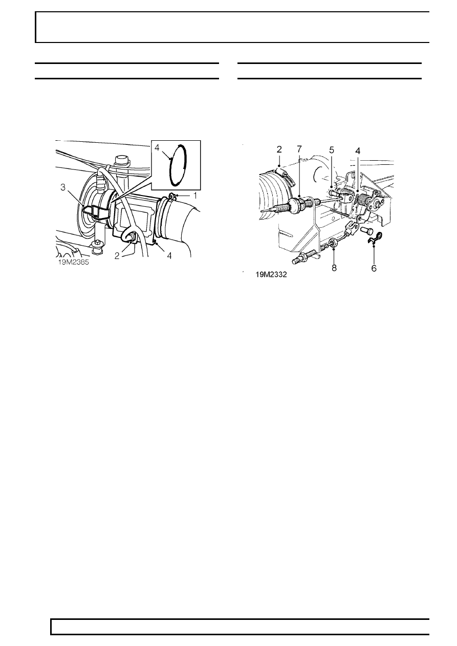
MASS AIR FLOW (MAF) SENSOR

Service repair no - 19.22.25

Remove

1. Loosen clip securing air intake hose to MAF

sensor and disconnect.

2. Disconnect multiplug from sensor.
3. Release 2 clips securing sensor to air cleaner.
4. Remove sensor, collect and discard ’O’ ring.

Refit

5. Clean sensor and mating faces.
6. Fit NEW ’O’ ring to sensor.
7. Fit sensor to air cleaner and secure clips.
8. Connect multiplug.
9. Connect air intake hose to sensor and tighten

clip.

PLENUM CHAMBER

Service repair no - 19.22.46

Remove

1. Disconnect battery negative lead.

2. Loosen clip securing air intake hose to plenum

chamber.

3. Disconnect air intake hose.
4. Remove split pin from throttle cable clevis pin.
5. Remove clevis pin.
6. Release and remove kick down cable clevis pin.
7. Release throttle cable from abutment bracket.
8. Remove front locknut from kick down cable.
9. Release cable from bracket.

SFI

13

REPAIR

10. Disconnect purge hose from plenum chamber.
11. Disconnect breather hose from plenum chamber.
12. Depress spring clip and disconnect TP sensor

multiplug.

13. Disconnect multiplug from IACV.
14. Remove 6 bolts securing plenum chamber to

inlet manifold.

15. Release plenum chamber from inlet manifold.
16. Fit hose clamp to water jacket coolant hoses.
17. Tighten clamp.
18. Position cloth to absorb coolant spillage.
19. Loosen clips securing coolant hoses to plenum

chamber.

20. Release hoses from plenum chamber.
21. Remove plenum chamber.
22. Place cloth over ram housing.

Do not carry out further dismantling if component
is removed for access only.

23. Remove 4 bolts securing water jacket to plenum

chamber.

24. Remove water jacket from plenum chamber.
25. Remove gasket from water jacket.
26. Move throttle linkage aside to gain access to

mounting bolts.

27. Remove 3 bolts securing throttle linkage to

plenum chamber.

28. Remove throttle linkage and collect spring.

29. Remove 2 screws securing TP sensor to plenum

chamber.

30. Remove TP sensor and collect clamping plate.
31. Remove 2 bolts securing IACV to plenum

chamber.

32. Remove IACV and collect gasket.

19

FUEL SYSTEM

14

REPAIR

Refit

33. Position throttle linkage and spring to plenum

chamber.

34. Fit spring to linkage.
35. Hold throttle open to gain access to mounting

bolts.

36. Fit and tighten mounting bolts to

8 Nm, 6 lbf ft.

37. Clean mating faces of TP sensor and plenum

chamber.

38. Fit TP sensor and engage spindle.
39. Fit clamping plate and tighten bolts to

2 Nm, 1.5

lbf ft.

40. Clean mating faces of IACV and plenum

chamber.

41. Fit gasket to IACV.
42. Fit IACV to plenum chamber and tighten bolts to

2 Nm, 1.5 lbf ft.

43. Clean mating faces of water jacket and plenum

chamber.

44. Position gasket to plenum chamber.
45. Fit water jacket to plenum chamber and tighten

bolts to

13 Nm, 10 lbf ft.

46. Remove cloth from ram housing.
47. Clean plenum and inlet manifold mating faces.
48. Position plenum chamber.
49. Connect coolant hoses to plenum chamber.
50. Tighten hose clips.
51. Loosen and remove hose clamp.
52. Remove cloth.
53. Apply a thin, uniform coating of Loctite 577

sealant to sealing face of plenum chamber.

54. Fit plenum chamber and tighten bolts to

24 Nm,

18 lbf ft.

55. Connect multiplug to TP sensor.
56. Connect multiplug to IACV.
57. Connect breather hose to plenum chamber.
58. Connect purge hose to plenum chamber.
59. Fit kick down cable to abutment bracket, fit

locknut and adust cable.

See AUTOMATIC

GEARBOX, Adjustment, Kickdown cable
adjustment

60. Connect throttle cable to abutment bracket.
61. Align throttle cable to lever, fit clevis pin and

secure with new split pin.

62. Align kick down cable to lever.
63. Fit and secure clevis pin.
64. Connect air intake hose and secure with clip.
65. Reconnect battery negative lead.
66. Top up cooling system.

THROTTLE POSITION (TP) SENSOR

Service repair no - 19.22.49

Remove

1. Disconnect multiplug from TP sensor.
2. Remove 2 screws securing TP sensor and

collect clamp plate.

3. Remove TP sensor.

Remove

4. Clean TP sensor and mating face.
5. Fit sensor ensuring drive engages with throttle

spindle.

6. Position clamp plate, fit screws and tighten to

2

Nm, 1.5 lbf ft.

7. Connect multiplug.

SFI

15

REPAIR

IDLE AIR CONTROL VALVE (IACV)

Service repair no - 19.22.54

Remove

1. Disconnect battery negative lead.

2. Disconnect multiplug from IACV.
3. Remove 2 bolts securing IACV to plenum

chamber.

4. Remove IACV.
5. Remove gasket and discard.

Refit

6. Clean mating faces of IACV and plenum

chamber.

7. Clean plunger on IACV and plunger seat on

plenum chamber.

8. Using a new gasket, fit IACV to plenum

chamber.

9. Fit and tighten bolts securing IACV to plenum

chamber to

2 Nm, 1.5 lbf ft.

10. Connect multiplug to IACV.
11. Reconnect battery negative lead.

FUEL FILTER

Service repair no - 19.25.02

WARNING: Spilling of fuel is unavoidable
during this operation. Ensure all
necessary precautions are taken to

prevent fire and explosion.

WARNING: Ensure fuel handling
precautions given in Section 01 -
Introduction are strictly adhered to when

carrying out the following instructions.

Remove

1. Depressurise fuel system.

See Adjustment,

fuel system depressurise

2. Clean area around hose connections to prevent

ingress of dirt into fuel system.

3. Clamp inlet and outlet hoses to reduce fuel

spillage when disconnecting.

4. Loosen 2 unions and disconnect hoses from fuel

filter.

CAUTION: Plug the connections.

5. Loosen bolt securing fuel filter to chassis

member.

6. Remove fuel filter.

Refit

7. Position NEW filter to chassis member,

observing direction of flow arrow stamped on
side.

8. Tighten bolt securing filter to chassis member.
9. Remove plugs.

10. Connect hoses to fuel filter and tighten unions to

30 Nm, 22 lbf ft.

11. Remove clamps from hoses.
12. Start engine and inspect for fuel leaks.


Content   ..  23  24  25  26   ..