Defender 90 NAS. Manual - part 23


  Index      Land Rover     Defender 90 NAS - service manual 1997 year


Search            


Content   ..  21  22  23  24   ..


Defender 90 NAS. Manual - part 23


19

FUEL SYSTEM

4

REPAIR

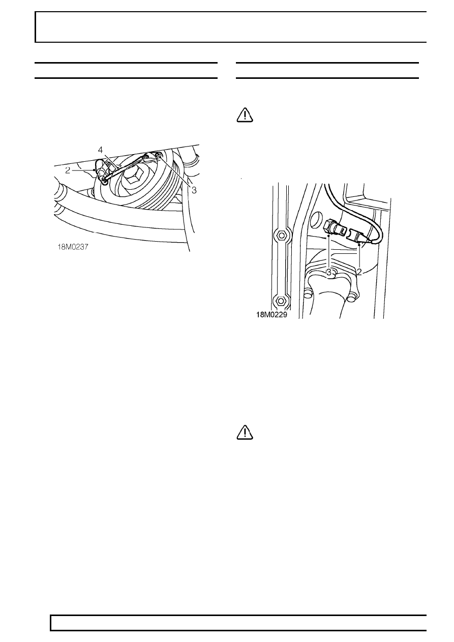
CAMSHAFT POSITION (CMP) SENSOR

Service repair no - 18.30.24

Remove

1. Disconnect battery negative lead.

2. Release sensor multiplug from clip and

disconnect multiplug.

3. Remove bolt securing sensor to front cover.
4. Remove sensor.
5. Remove and discard ’O’ ring.

Refit

6. Clean sensor and mating face on front cover.
7. Lubricate and fit ’O’ ring to sensor.
8. Fit sensor, fit bolt and tighten to

8 Nm, 6lbf ft.

9. Connect sensor multiplug and secure to bracket.

10. Reconnect battery negative lead.

KNOCK SENSOR - LH

Service repair no - 18.30.28

CAUTION: Due to the sensitivity of the
sensor, do not apply tape or sealant to
sensor threads.

Remove

1. Raise vehicle on ramp [hoist].

2. Depress spring clip and disconnect multiplug

from LH knock sensor.

3. Remove sensor from engine.

Refit

4. Clean mating faces of sensor and engine.
5. Fit sensor and tighten to

16 Nm, 22 lbf ft.

CAUTION: Failure to tighten sensor to
correct torque will result in malfunction or
sensor damage.

6. Connect multiplug to sensor.
7. Lower vehicle.

SFI

5

REPAIR

KNOCK SENSOR - RH

Service repair no - 18.30.30

CAUTION: Due to the sensitivity of the
sensor, do not apply tape or sealant to
sensor threads.

Remove

1. Raise vehicle on ramp [hoist].

2. Remove bolt securing starter motor heat shield

to engine RH mounting.

3. Release heat shield clip from starter solenoid.
4. Move heat shield aside to gain access to knock

sensor.

5. Depress spring clip and disconnect sensor

multiplug.

6. Remove sensor.

Refit

7. Clean sensor and mating face.
8. Fit sensor and tighten to

16 Nm, 12 lbf ft.

CAUTION: Failure to tighten sensor to
correct torque will result in malfunction or
sensor damage.

9. Connect multiplug to sensor.

10. Manoeuvre heat shield into position.
11. Secure heat shield clip to solenoid.
12. Align heat shield to mounting and secure with

bolt.

13. Lower vehicle.

19

FUEL SYSTEM

6

REPAIR

INERTIA FUEL SHUT OFF SWITCH

Service repair no - 19.22.09

Remove

1. Disconnect battery negative lead.

2. Disconnect multiplug from inertia fuel shut off

switch.

3. Remove 2 screws securing shut off switch to

mounting bracket.

4. Remove shut off switch.

Refit

5. Position fuel shut off switch to mounting bracket

and secure with screws.

6. Connect multiplug to inertia switch.
7. Reconnect battery negative lead.

RELAY MODULE

Service repair no - 18.30.71

Remove

1. Remove 2 screws securing ECM cover.
2. Remove cover.

3. Remove 2 screws securing ECM.
4. Release ECM from 2 lower retainers and move

aside for access to relay module.

5. Release relay module from bracket.
6. Disconnect 2 multiplugs from module.
7. Remove relay module.

SFI

7

REPAIR

Refit

8. Position relay module
9. Connect multiplugs and secure module to

bracket.

10. Position ECM and secure to lower retainers.
11. Fit and tighten screws securing ECM.
12. Fit cover and tighten screws.

AIR CLEANER

Service repair no - 19.10.01

Remove

1. Loosen clip securing intake hose to MAF sensor

and disconnect hose.

2. Disconnect multiplug from IAT sensor.
3. Release 2 toggle clips and release MAF sensor

from air cleaner.

4. Remove ’O’ ring and carefully place sensor

aside.

5. Remove 3 nuts securing air cleaner to mounting

rubbers.

6. Remove air cleaner assembly.

Do not carry out further dismantling if component
is removed for access only.

7. Remove IAT sensor.

Refit

8. Clean threads of IAT sensor and fit sensor to air

cleaner.

9. Position air cleaner to mountings and fit and

tighten nuts.

10. Clean MAF sensor and mating face.
11. Fit NEW ’O’ ring, fit sensor and secure toggle

clips.

12. Connect multiplug to IAT sensor.
13. Connect air intake hose and tighten clip.


Content   ..  21  22  23  24   ..