Defender 90 / 110 / 130. Manual - part 193
F
U
EL
S
YSTEM
CARBURETTER OVERHAUL
S.U.
HIF 44
-
Right
hand
DISMANTLE
Remove the carburetters from the engine and clean
t h e
exteriors with a suitable solvent.
2. Remove the two nuts and spring washcrs and
withdraw
t h e
air intake adaptor and joint washer.
3. Unscrew and remove
piston damper assembly
and drain the oil.
4.
Remove the three screws and lift-off
t h e
suction
chamber complctc with piston and spring.
5 . Remove
spring clip from the top of the piston
rod and withdraw the piston and spring.
6.
Unscrew the fuel metering needle guide locking
screw. If t h e needle cannot be removed from the
piston with the fingers, hold the needle as close to
the
piston as possible, in a soft jawed
and with
a sharp pull withdraw the needle, guide and spring
assembly
.
7. Remove the four screws and withdraw the float
chamber cover plate and sealing ring.
Remove the jet adjusting lever
screw and
spring.
Withdraw the jet complete with
bi-metal lever
and seperate the lever from t h e jet.
Unscrew and remove the float pivot spindle and
plain washer, and remove the float.
11.
Lift-out the
valve.
12. Unscrew and remove the needle valve and filter.
13.
Unscrew and
the jet bearing nut.
Invert
carburetter body to allow the jet bearing
to
fall out. If the bearing sticks, carefully tap
it
out
from
bridge side.
.
15. Remove the piston guide
Remove the suction chamber-to-body sealing ring.
17. Unscrew and remove the mixture adjusting screw
and seal. Use thin nosed pliers to finally withdraw
screw.
18.
Bend-back the cam lever nut lock tabs and remove
the nut and lock washer.
19. Removc the cam lever and spring.
20. Remove the end seal cover and seal.
21. Remove the two screws and withdraw the cold start
valve body and seal together with the valve spindle.
Also
collect the paper joint washer.
22. Note the position
of
the throttle levers and return
spring.
23. Bend-back the lock washer tabs and remove the
throttle
nut.
24. Removc the lock washer, bush washer and throttle
actuating lever.
25.
the throttle return spring and remove the
throttle adjusting
from the throttle butterfly
spindle and remove the return spring.
26. Hold the butterfly closed and mark the relationship
of
t h e
butterfly to the carburetter flange.
27. Remove the butterfly two retaining screws and
withdraw the
from the spindle.
.
28. Withdraw the throttle butterfly spindle from the
carburetter body together with
two seals.
29. Clean all components with petrol
or de-natured
alcohol ready for inspection.
Do not use abrasives
for the removal of stains
or deposits.
INSPECTION
30. Examine the throttle spindle and bearings for
excessive axial
31. Check the float needle and seating for wear and the
float for punctures and renew
if
necessary.
32. Check the condition of all
rings
and joint washers and renew if necessary. The float
seal must be renewed.
33. Examine the carburettcr body for cracks and
damage.
Ensure that the inside of the suction chamber is
clean and fit the piston into the chamber without
the spring. Hold the assembly horizontally and
spin
the piston. The piston should spin freely i n the
suction chamber without any tendency to stick.
35.
the metering needle
wear, scores and
distortion. Check also that i t has the correct
designation number
-
see Engine
Data,
Section
05.
36. Examine the bi-metal jet
for cracks.
37. Check all springs for cracks and distortion.
ASSEMBLE
Fit throttle butterfly
38.
Fit the throttle spindle to the carburetter body and
the throttle disc into the spindlc in its original
position. Secure t h e disc with new screws and
ensure that before tightening the throttle disc is
correctly positioned and closes properly. Splay the
split ends of
the
screws to
turning.
39. Fit new seals to both ends
of
throttle spindle
that they are fitted the
way round.
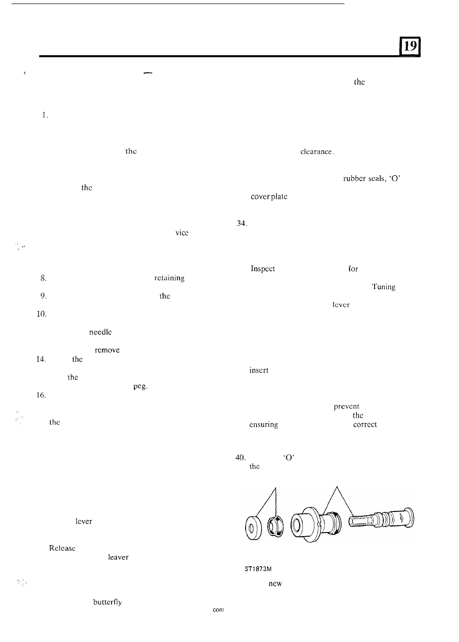
Fit cold start assembly
Fit a new
ring to the valve body and assemble
valve spindle to the valve body.
43
40
41.
Fit a
paper joint washer to the valve noting
that the half-moon cut-out in the washer is
clearance for the top retaining screw.
tinued
3