Defender 90 / 110 / 130. Manual - part 188
...
. .
.
...
...
MANUAL
GEARBOX
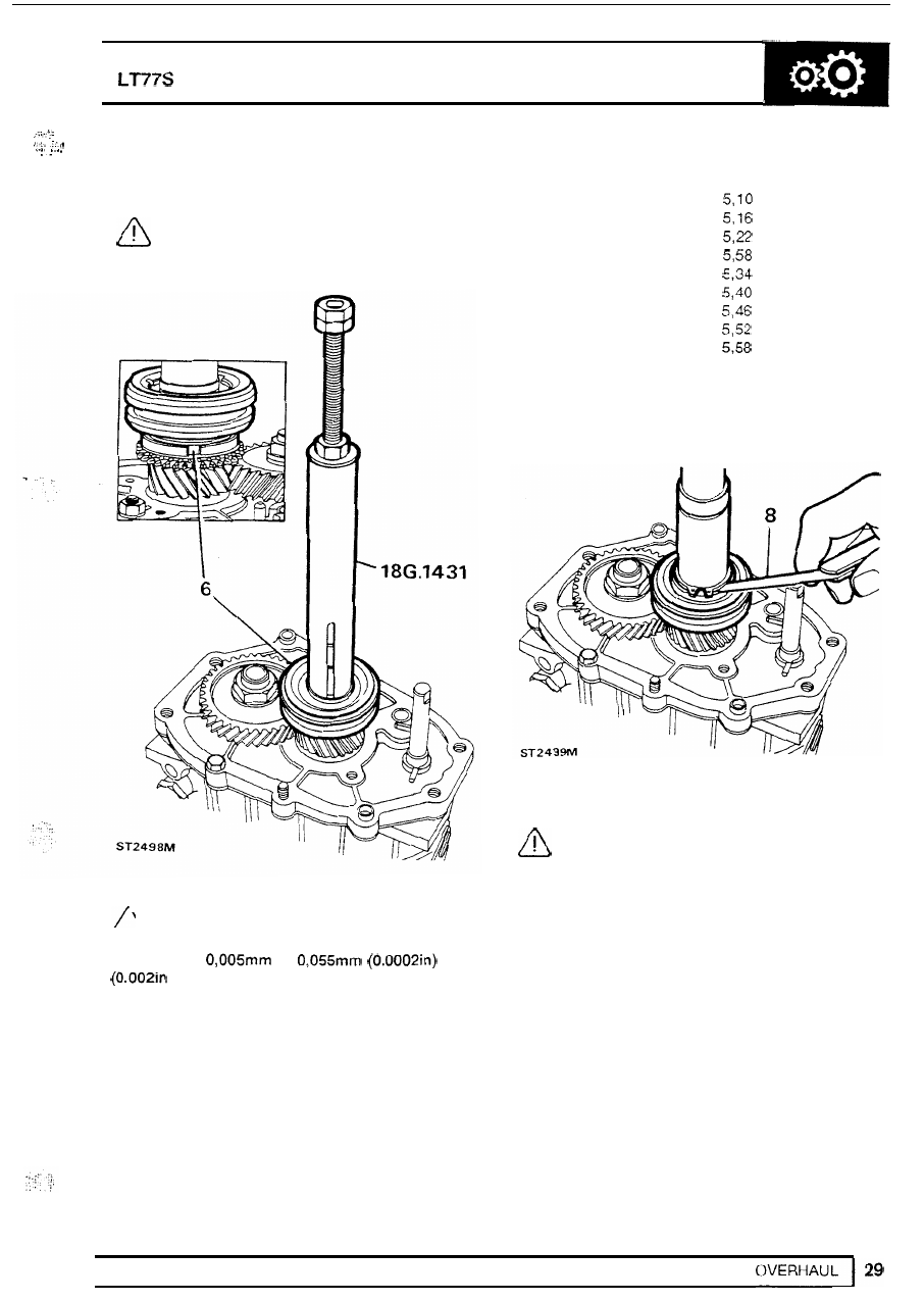
6.
Press fifth gear synchromesh assembly
to
mainshaft using
18G 1431.
CAUTION: Before pressing the assembly
locate
in
the baulk ring slots.
fully home, ensure that the slipper pads
Part number
Thickness
FRC
5284
FRC
5286
FRC
5288
FRC
5290
FRC
5292
FRC
5294
FRC
5296
FRC
5298
FRC
5300
FRC
5302
5.64
7.
Fit the thinnest washer and secure with circlip.
8.
Measure clearance between circlip and washer,
9.
Tighten layshaft stake nut using 18G
1205.
CAUTION: The practice of locking gears
not acceptable due t o
high
torque figure
to
provide
a
restraint
to
tighten the
nut
is
required.
NOTE:
Only
limited movement
of
the
synchromesh inner member on the
main-shaft is permissable. The maximum
clearance is
to
to
and t o achieve this the following
selective washers are available.