Defender 90 / 110 / 130. Manual - part 172
DEFENDER
ENGINE
Fitting
rear cover
9.
Fit the rear cover also using a new gasket and
secure with six bolts tightened t o t h e correct
torque.
Fitting
fuel l i f t
pump
10. Check that t h e lift pump
is serviceable and refit
using a new gasket, ensuring that t h e pump
actuating lever locates correctly o n t o the
camshaft
.
,
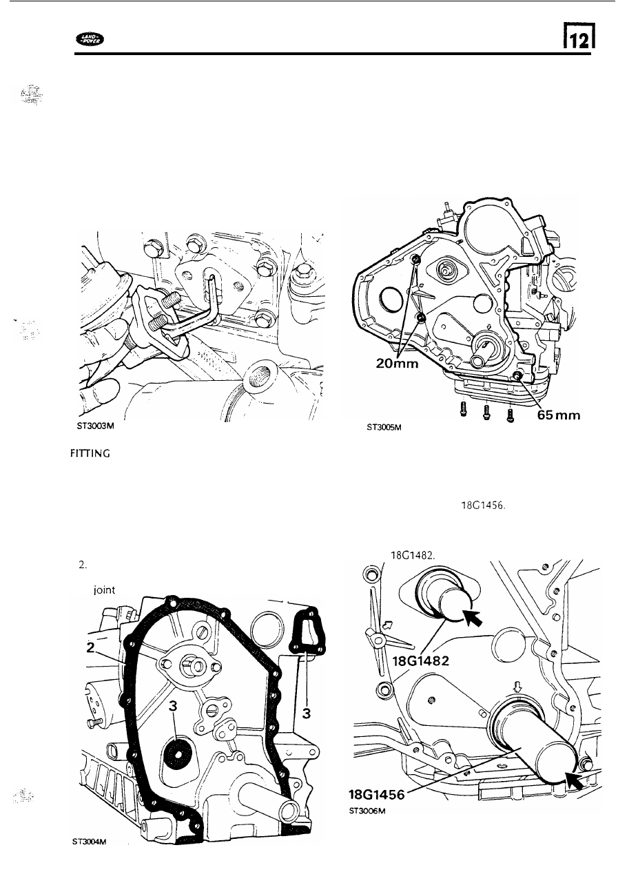
FRONT
COVER
TIMING BELT AND GEARS
1.
Clean the front cover and remove t h e
crankshaft and camshaft oil seals taking care
not t o damage the seal housing. Examine t h e
cover
for
damage, cracks and distortion. Check
the mating
face of the cylinder block and the
cover plate f o r burrs.
Clean the front face
of the cylinder block and
use a little grease t o hold in position a new
washer.
3. Also
fit a new joint washer t o the coolant
aperture and
to the tapped hole for the jockey
pulley clamp bolt.
4.
Fit
the front cover locating it over the single
stud and secure with the three retaining bolts
tightening evenly
to the correct torque. The
correct bolt length for each hole
is given in
the following chart.
Front
cover seals
5. Lubricate a new crankshaft oil seal. With the lip
side leading, drive-in the seal, squarely, using
special service tool
6. Similarly, lubricate and drive-in a new camshaft
oil seal, lip side leading, using special service
tool
67