Defender 90 / 110 / 130. Manual - part 168


  Index      Land Rover     Defender 90 / 110 / 130 - service repair manual


Search            


Content   ..  166  167  168  169   ..


Defender 90 / 110 / 130. Manual - part 168


DEFENDER 

ENGINE 

5 .  

Lift-out the crankshaft either by  hand 

or hoist. 

If 

a  hoist  is  used  be 

sure 

to 

insert  adequate 

protection  between  the sling and joumals 

to 

avoid  damage. 

6 .  

Remove the mainbearing  upper shells  from the 
cylinder block. 

7. 

Remove the  two thrust  washers  from  each side 

of the centre bearing  location. 

8. 

Remove  the four cylinder lubrication, jet  tubes. 

CYLINDER  BLOCK 

INSPECTION 

AND 

OVERHAUL 

Inspection 

Degrease the  cylinder block  and  carry o u t  a 

thorough visual  examination  checking 

for 

cracks and damage. To  check  each  main 
bearing  cap and its location on  the cylinder 
block,  fit  the  bearing  caps without  the  bearing 

shells. 
Fit  the  bolts  and tighten  to the correct  torque, 
then remove o n e  bolt  from  each  bearing  cap 

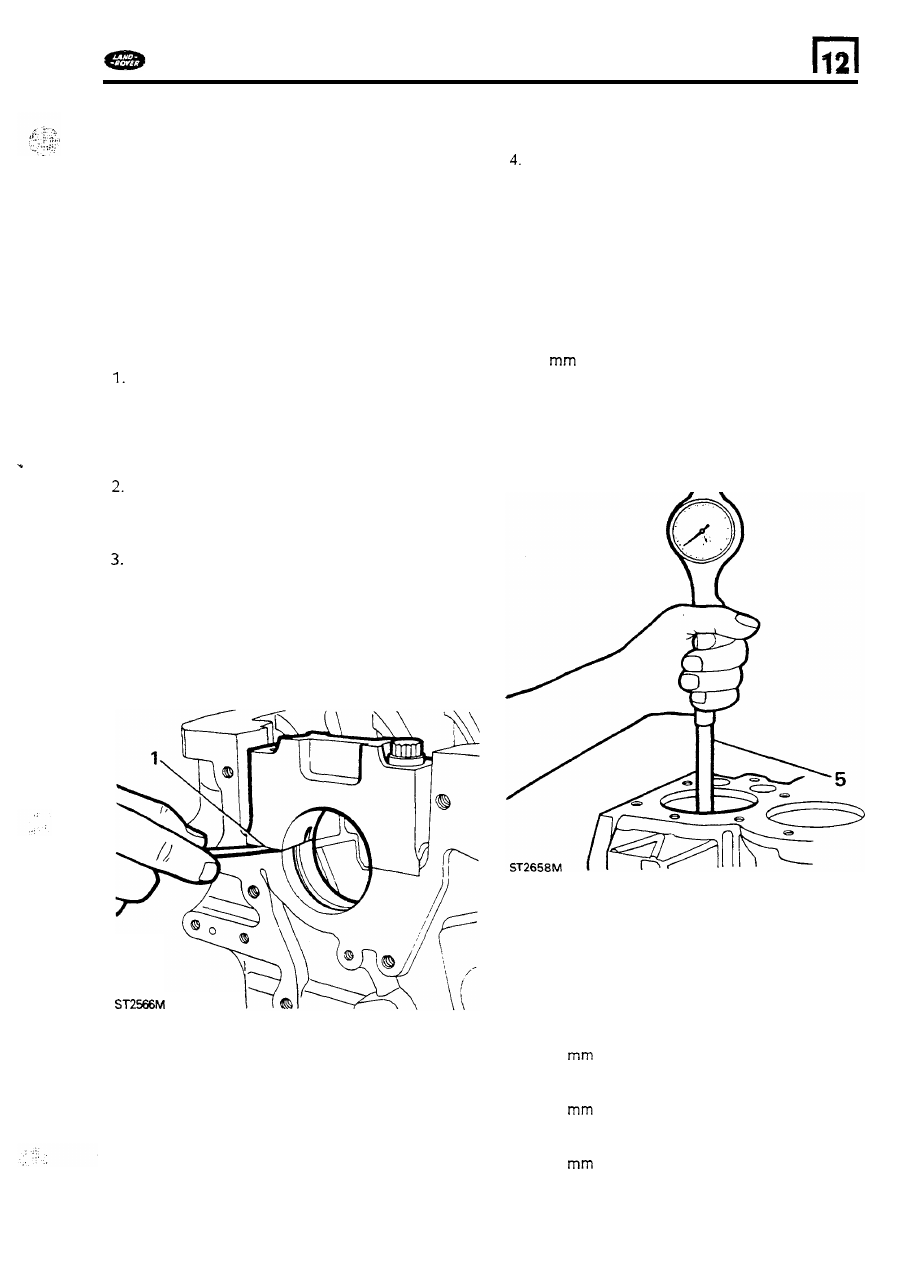
and  check with  a feeler gauge that  n o  
clearance exists at the joint  face  as illustrated. 

clearance indicates  either a bent  bolt, 

damaged dowl,  distortion 

of  the caps o r  block, 

o r  

that  the cap has  been  filed  or machined  in 

an attempt t o  reduce any clearance d u e  t o  
wear in  the bearings.  Main  bearing  caps are 
not  available  separately  from  the cylinder block 

therefore  any  clearance  should  be investigated 
and  rectified  or the block  renewed. 

Cylinder  bores 

Measure  the cylinder  bores 

for ovality,  taper 

and  general wear,  using  any suitable 
equipment.  However,  an inside micrometer 

is 

best 

for checking ovality  and a  cylinder gauge 

for taper.  Check the  ovality 

of each bore by 

taking  measurement  at  the t o p  of  t h e  cylinder 
just  below the ridge  at two points  diametrically 
opposite. 

5.  The  difference between  the 

two 

figures 

is  the 

ovality at the t o p  

of 

the bore.  Similar 

measurements should  b e  made approximately 

50 

(2.0 

ins) up from the  bottom 

of  the 

bore 

so 

that t h e  overall  ovality  may 

be 

determined. The taper 

of  each cylinder is 

determined  by  taking  measurements  at the t o p  
and  bottom 

of  each bore at right  angles 

to the 

gudgeon pin  line,  the difference  between the 
two 

measurements  is the taper. 

To 

establish  maximum  overall 

bore wear,  take 

measurements  at as many  points  as  possible 
down the bores  at  right  angles t o  the gudgeon 
pin  line. The  largest  recorded  figure 

is  the 

maximum wear  and  should  b e  compared  with 
the original  diameter 

of  the cylinder  bore. 

Maximum  permissible  ovality 

0,127 

(0.005 

in). 

Maximum  permissible taper 

0,254 

(0.010 in). 

Maximum  permissible  overall wear 

0,177 

(0.007  in). 

51 

If 

t h e  above figures are exceeded the cylinders must 

condition 

of 

the bores and t h e  amount 

of  wear. 

if 

t h e  overall wear,  taper and ovality 

are well  within  the acceptable limits and  the original 
pistons are serviceable n e w  piston  rings  may  be 

fitted.  It 

is  important  however,  that 

bores are 

deglazed,  with  a  hone, t o  give a cross-hatched 
finish  t o  provide  a seating  for the new ring. 

b e  rebored  or sleeved  depending  upon  the 

ENGINE 

DEFENDER 

Fitting cylinder sleeves 

Cylinder bores that  cannot  b e  rebored  can  be 
restored  by  fitting 

sleeves t o  enable standard  size 

pistons t o  

be fitted.  Sleeving o n e  cylinder  only will 

distort the adjacent  bore 

so sleeving must  b e  

carried  o u t  in  pairs,  i.e.  cylinders 

and  2  or 3 and 

4. 

6.  Machine the cylinder bores t o  accept the 

sleeves t o  94,425 

0,012 

(3.7175 

0.0005 

in). This will  give  the sleeve a  0,076 t o  

0,114 

t o  0.0045  in) interference  fit. 

Press  the sleeves squarely  into the  bore using 

a pressure 

of  two  o r  three tons.  Excessive 

pressure could  damage the sleeve and  cylinder 
block. 

The sleeves must not b e  proud 

of  the cylinder 

block top face 

or  more than 

(0.10 

in) 

below the surface. 

7, 

Bore  and  hone the sleeves t o  accomodate the 

pistons with  the required  clearances, see 
piston  and connecting rod  examination. 

Camshaft  bearings 

8. 

Measure the intemal  diameter 

of 

each 

camshaft bearing at several  points  using  an 
internal  micrometer. 

comparison 

of  the bearing  diameters with  those 

of 

t h e  respective  camshaft  joumals will  give the 

amount 

of 

clearance.  The  bearings  should be 

renewed 

if 

the clearance exceeds 

0,0508 

(0.002 

in). 

Or, 

in  any event, 

if 

they are scored or  pitted. 

This work  should  only b e  entrusted t o  

line 

boring 

specialists. 

It  is  vital  t o  thoroughly wash  the cylinder block  after 
machining  t o  remove  all  traces 

of  abrasive  material, 

ensuring that  all  oil  galleries are clean. 

Check  crankcase  main  bearings 

Discard 

scored, pitted,  cracked and w o m  bearing 

shells. To determine the maximum  wear,  assemble 
the main  bearing shells and caps t o  t h e  crankcase 
and  tighten  the bolts t o  the correct torque figure. 

Using  an  inside  micrometer,  measure each  bearing 

at several  points  and  note t h e  greatest  figure. The 
maximum  wear 

is  t h e  difference between this figure 

and the smallest diameter 

of  the corresponding 

crankshaft  journal. 

The main  bearing  running  clearance 

is  given  in  t h e  

data section. 

1. 

Degrease t h e  crankshaft  and  clear o u t  t h e  oil 

ways which  can  b e c o m e  clogged  after long 
service. 

bearing joumals for obvious wear,  scores, 

grooves and overheating. 

decision  at this 

stage should 

be made as t o  whether t h e  

condition 

of  t h e  shaft is worth  continuing with 

a more detailed examination. 

ovality  and taper 

of  each main  bearing  journal 

and  crankpin  as follows. 

2.  Examine visually,  the crankpins and  main 

3. 

With  a micrometer, measure and n o t e  the 

4. 

Ovality 

Take 

two 

readings at right  angles t o  

each other at various  intervals.  The maximum 
ovality  must n o t  

exceed  0,040 

in). 

other at both  e n d s  

of 

t h e  main  bearing journal 

and  crankpin. The maximum  permissible  taper 
must  not  exceed 0,025 

in). 

To check  for straightness,  support t h e  front 

and  rear main  bearing  joumals  in 

blocks 

and 

a  dial  indicator to check t h e  

run-out at the centre main  bearing journal. 
Run-out  must  not 

exceed 

0,076 

(0.003 in) 

taking  into account any ovality 

t h e  centre 

journal.  The overall wear limit  should  not 
exceed 0,114 

(0.0045  in) 

f o r  

main  bearing 

joumals  and 

0,088 

(0.0035 

in) for 

crankpins. 

7. 

crankshaft w o m  beyond t h e  limints 

of 

maximum  taper,  ovality and  overall  wear,  can 
b e  ground 

(0.010 in). 

Taper 

Take two  readings parallel  t o  each 

When grinding  t h e  crankshaft main  bearing  and 
crankpin  joumals,  rotation 

of  the  grinding wheel  and 

crankshaft  must b e  in  the same direction, 
anti-clockwise,  viewed  from  t h e  flywheel e n d  

of  the 

crankshaft. 

52 

DEFENDER 

ENGINE 

finishing 

of  the joumals  should be achieved  by 

using  a static lapping  stone with  the crankshaft 
rotating  in  a clockwise  direction viewed  from  the 

flywheel end 

of the crankshaft. 

It 

is 

important  to ensure that,  when  grinding,  the 

s t o n e  travels  beyond  the e d g e  

of  the joumal 

' A  

t o  

avoid  formation 

of 

a step 

'B' 

as 

illustrated. 

Also 

care 

must  be taken  not t o  machine  o r  damage the fillet 
radii 

It 

is  vital  t o  thoroughly wash  the crankshaft  after 

machining  t o  remove all  traces 

of  abrasive  material, 

ensuring  that  all 

oil  galleries  are clean. 

Pistons 

and 

connecting 

rods 

The following  checks relating  t o  pistons  and  rings 

must  also be carried out prior t o  fitting  new  pistons 
t o  rebored  and sleeved cylinder  blocks.  Until  it  is 

decided 

if 

new components are required  all  parts 

must 

be  kept  in  their related  sets and the position 

of each piston  to its connecting rod  should  be 
noted. 

1. 

Remove the piston  rings  and gudgeon  pin 

from each piston  and  detach the connecting 
rod. 

2.  Original  pistons 

Decarbonise and  degrease all 

components and  carry out a visual  examination 
of  the piston  and  rings  and  discard  any which 

are unserviceable.  Pistons which  appear 
serviceable should be subjected t o  a more 
detailed  examination  described  under  'New 

Pistons'. 

New pistons 

Original pistons  fitted 

to  new 

engines 

at 

the 

to 

facilitate assembly.  The  grade letter on the 
piston  crown  should  be ignored  when 
ordering new  pistons. 

Genuine Land  Rover service standard  size  pistons 
are supplied 0,025 

(0.001 

in) oversize 

to allow 

for production 

o n  new  engines. When 

fitting new pistons t o  a standard  size cylinder,  the 
bores must  be honed  t o  accomodate the pistons 

with  the correct clearances.  In  addition  Land  Rover 
pistons  are available 

and 

(0.020 and 

0.040 

in) oversize 

for fitting t o  rebored  cylinders. 

Clearance  limits for new standard size  pistons in  a 
standard  cylinder  bore  measured  at  right angles 

to 

the gudgeon pin  are in  t h e  data  section. When 
taking  the following  measurements the  cylinder 
block  and pistons  must  b e  the same temperature  to 
ensure accuracy. 

4. 

Using  a suitable micrometer  or vernier measure 
the  pistons  at the bottom 

of  the skirt  at  right 

angles t o  the gudgeon pin. 

53 

ENGINE 

DEFENDER 

5.  With  an  inside micrometer or cylinder gauge 

measure  the diameter 

of  the bore at 

approximately half-way  down and note the 
reading. 

6 .  

The clearance is  determined  by  subtracting the 

7. 

If 

gauge equipment is  not available  the 

piston  diameter from the bore diameter. 

clearance can  b e  assessed by  placing  a long, 
suitably sized, 

feeler 

gauge down the thrust 

side 

of 

the bore and  inserting  the appropriate 

piston,  'upside  down',  in  the bore and  position 

it 

with  the gudgeon  pin  parallel  t o  the 

crankshaft axis.  Push  the piston  down the bore 
and  stop at  the tightest  point  and whilst 
holding the piston  still,  slowly withdraw  the 
feeler gauge. 

If 

a steady resistance 

of 

approximately 

2,5 

( 6  

is  felt, t h e  

clearance 

is 

satisfactory. 

Piston  ring 

gaps 

9. 

With  the appropriate feeler gauge check 

all 

the 

ring  gaps in  turn,  including  t h e  

oil 

control 

rings. 

The correct gaps are  listed  in  t h e  data section.  If  any 

gap 

is  less than that specified, remove the ring,  and 

file  the e n d s  square,  whilst  holding  the ring  in  a 
filing 

jig  or vice.  Should any gap b e  excessively wide 

and not  likely 

to  close u p  t o  within  the 

specified 

limits when  hot,  an oversize  ring  should  b e  fitted. 

O n c e  t h e  rings  have  been selected for a  particular 
cylinder and  piston  ensure that  they are not again 
mixed  up. 

Piston  ring groove clearance 

It 

is  important  that the groove clearances are 

correct.  Rings  that are t o o  tight  may  bind  o r  
fracture when hot and cause 

loss of 

compression. Excessive  clearance  allows t h e  
rings  to 

rock  in  t h e  groove and  may  result  in  a 

pumping  action  and excessive oil 

consumption. 

8. 

When checking t h e  piston  ring  gap in  worn 

bores which  are within  the acceptable taper 
and  ovality limits,  t h e  ring  must  be inserted 

squarely into the bottom 

of  the cylinder at the 

lowest point 

of 

the piston  travel.  To  ensure 

squareness push  the  ring  t o  the correct 
position  using  a piston. 

54 


Content   ..  166  167  168  169   ..