Defender 90 / 110 / 130. Manual - part 166
DEFENDER
ENGINE
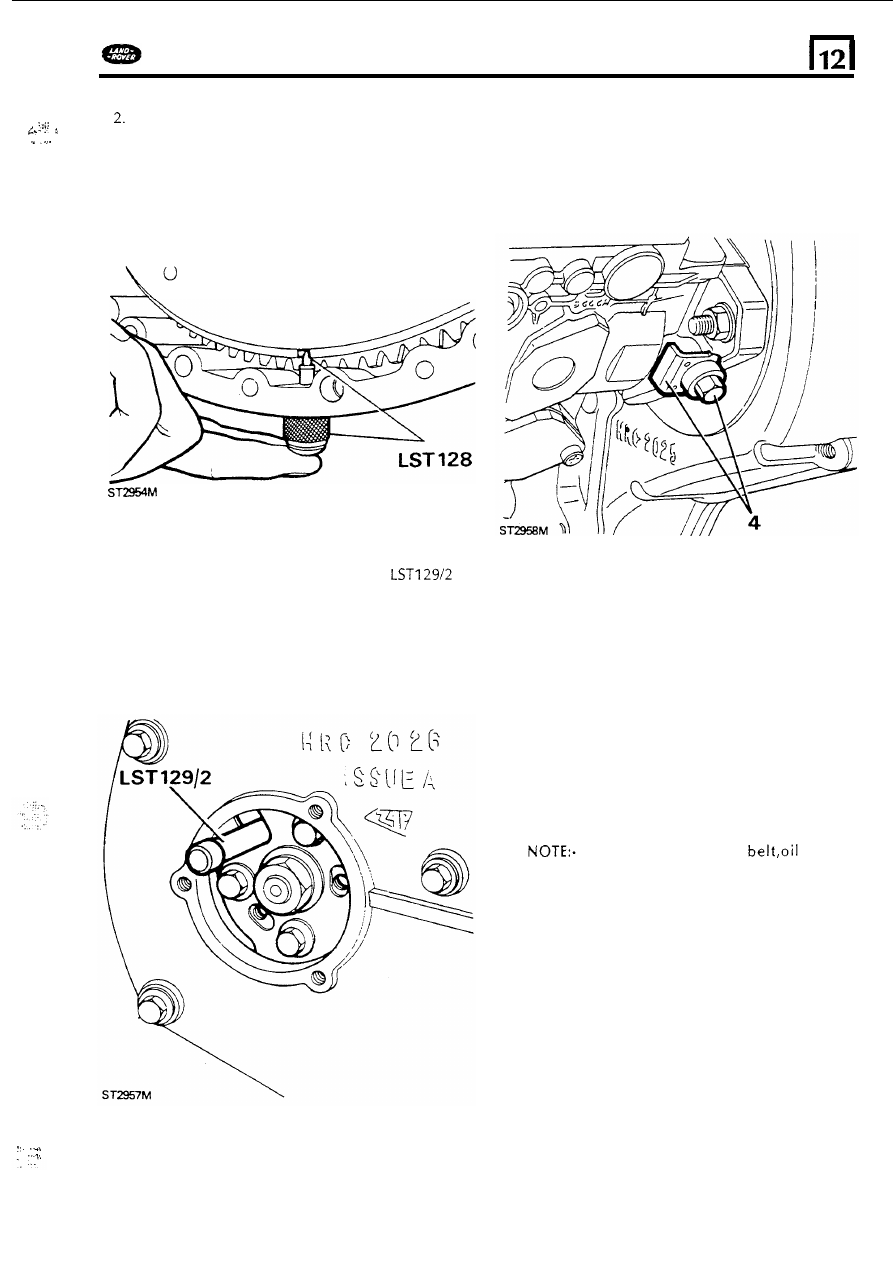
Now screw the body
of the timing pin tool LST
128
into the flywheel housing and check that
the pin can
be inserted in t o the appropriate
slot in the flywheel periphery. Note that there
are
two slots in the flywheel o n e being wider
than the othe. The narrowest
slot determines
TDC
for this engine and it
is therefore
important that the correct slot is used.
4.
To
lock the pump, Slacken the locking screw
anticlockwise and remove the inhibiting plate.
Turn the screw clockwise t o
lock the pump
shaft. Remove the timing pin from the flywheel
housing.
0
3.
Remove the three screws t o release the
injection pump access cover from the front
cover plate and insert the locking pin
through the
"U"
shaped cut-out in the pump
hub and into the hole in the pump body. This
will confirm that the injection pump
is correctly
timed in relation t o the valves and crankshaft
and can
be locked ready for removing. Leave
the pin in position in the pump.
CAUTION:
It is important t o ensure that
o n c e t h e injection p u m p has been locked
n o attempt must b e m a d e t o rotate it.
Therefore take care not
to
allow t h e
crankshaft t o b e turned until t h e p u m p has
been removed.
If
renewing t h e timing
seals
o r gears (with t h e cylinder head fitted) and
there
is any possibility that t h e crankshaft
will need t o b e rotated after removal
of
t h e
timing belt, it would b e advisable t o remove
t h e rocker shaft. This will prevent t h e
pistons contacting t h e valves as t h e
crankshaft is turned.
If
necessary,
See
rocker shaft removal.
..
..
.
43